|
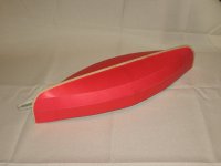
One-Sheet Baby Canoe
Part 1 |
|
| By Gaetan
Jette - Sherbrooke, Canada |
Part
1 - Part 2
- Part 3
- Part 4
Introduction
It is often recommended, for first
time boatbuilders, to start with a small project.
That's one advice I followed: I built a one-sheet
boat. Both the building and storage space available
to me could not handle anything much bigger anyway.
Designing your own boat, however, is
not recommended by experts. Well, since I am as much
interested in the design process as in using that
boat, I couldn't resist the challenge. My thinking
was, this would be a great learning experience, and
if the boat proved to be a failure, the investment
in time and money would not have been too great. The
project took 2 years to complete: one year to draw
it, one year to build it. That took longer than expected,
but I didn't fully know how to draw a boat when I
started this project. In particular, I had to learn
how to do a surface development for the hull. As for
the building, the sanding took forever, it seems.
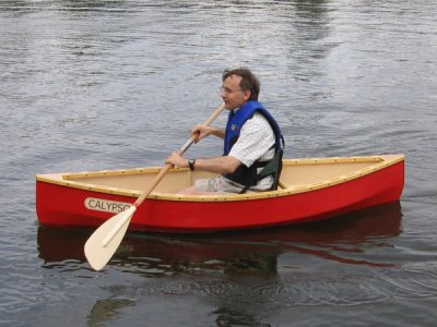
I am pleased with the way the boat
looks. Performance wise, though, it is quite tippy,
at least for a novice paddler like me. But it was
a great learning experience.
History
of the design
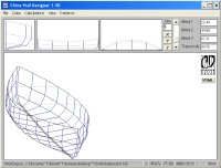
I did not wake up one day and just
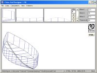
decided to build a one-sheet canoe, though. What happened
was this: a few years ago, I started to play with
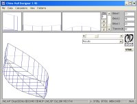
Gregg Carlson's Hull Designer program. During the
same period, there were quite a few one-sheet designs
presented on the Duckworks web site. I thus chose
to learn that program by concentrating on a one-sheet
double-ender. Why a double-ender, do you ask? Well,
first, this is an easier design to figure out. If
the crew sit right in the middle, you get perfect
trim. Since, as far as I know, the Hull Designer program
doesn't adjust trim, this was easier to deal with
than on a transom boat. Second, maximizing the length
of the bottom and side panels seems easier if you
don't have to also fit a transom on that single sheet.
Third, I was aiming more at good gliding performance
rather than the highest displacement possible, as
with a pram shape.
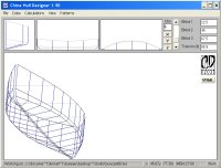
The first hull looked like this:
 |
 |
Simple
flat-bottom double-ender |
This is essentially a flat-bottom hull
with vertical top sides. That's about the simplest
shape there is for a boat: all the curves are basically
circle arcs. The reason for using vertical top sides
without any flare was to achieve maximum waterline
length. With some flare, the chine is typically shorter
than the sheerline. The sheer curve is achieved by
drawing a curved plank, rather than using a mostly
straight plank with a good amount of flare.
Although such a hull shape doesn't
look too bad, it is hard to achieve a fair displacement
and adequate freeboard at the same time. I decided
to go from a flat to a V-bottom, to see if this would
increase displacement. I also started to make cardboard
models of the most promising models, using empty cereal
boxes.
The hull shape did look a bit better,
despite being drawn with vertical sides. The displacement
was a bit better but still too low: my target was
250 pounds. More rocker in the bottom would have been
necessary to keep the stem above the waterline. But
this would have meant less freeboard amidships. As
a novice designer, I wasn't sure how much freeboard
was enough, but more seemed better.
I decided then to got for a second
chine, hoping for better results. I tried several
variations of plank shape for the new middle plank.
The one variation that seemed to go somewhere was
this one:
By making the middle plank narrower
in the center and wider at the extremities, this left
more plywood for the midship area of the bottom planks.
This also flattened the keel line, burying the stem
somewhat underwater. This would be bad for a flat-bottom
boat, but good for a multi-chine hull. This improves
tracking and adds a little more displacement. The
shape was starting to look a lot like a canoe. It
is at that point that I decided to seriously attempt
to draw a canoe.
The middle plank was quite narrow on
this model, looking more like it was just softening
the edge of a hard chine hull. For the next model,
I decided to use a wider middle plank. I looked more
seriously at optimizing the midship cross-section.
Hannu Vartalia's online essays, in particular, come
to mind. I also checked what were typical dimensions
for a canoe. An online version of W.P. Stephens' book
'Canoe and Boat Building' proved useful for that.
It might have best to go look at real canoes, though.
I might have noticed that typical canoes have a flatter
midship section than what I was drawing. Anyway, the
next model looked this:
All that was missing for an authentic
canoe look on this model was a round stem/stern and
a round bilge. The round bilge couldn't be done in
plywood, as far as construction was concerned. The
round stem, I couldn't do using Hull Designer. You
can approximate the rounded look by creating multiple
chines, but that program, as far as I know, is not
suited for drawing perfectly round stems (you can't
ask too much from a free program). At that point I
moved to another program for drawing my hull models.
I used TurboCAD, a general purpose drafting program
I was somewhat familiar with. I say somewhat, because
although that program can handle drawings in 3D, I
was not comfortable with the 3D interface of the program.
Instead, I drafted my next hulls in 2D, much like
the way hulls lines are drawn on a sheet of paper.
This meant much slower progress, having to deal with
surface development manually. One book, by S.S. Rabl,
titled "Ship and Aircraft Fairing and Development"
proved helpful to understand the process, which previously
was a mystery for me. It nevertheless took several
drafts, due to various mistakes and problems, before
I could build a cardboard model.
The round stem gave me some trouble:
a surface can be developed if it bends in one direction
only. With a hull shape created by an arc lengthwise,
near the bow the plywood would have to bend both horizontally
and vertically: not possible. The solution was to
use an arc for most of the boat length, but finish
the last 9 inches near each end with a straight line.
This way the surface would end up closer to what plywood
can handle: it would only have to bend vertically
to follow the curved stem.
The stem curve was achieved by using
a portion of an oval shape, with a straight section
for the top plank. That curve looked fine in profile,
but the lower part of the bow seemed too full, especially
when looking at the model. If you look closely at
the hull lines, in the profile view, the bottom chine
is almost a straight line. It didn't look too bad,
but it certainly looked odd in profile view. I thought
it would be best to raise that chine near the bow
and stern. A couple drafts later, I had arrived at
this:
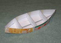
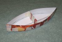
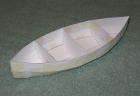
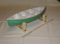
I built the model on a larger scale
this time: I printed the pattern on paper and glued
them on cardboard. The keel, frames and gunwales were
cut from 1/8th inch plywood. At this scale, this was
equivalent to 3/4-inch stock. I even made a wooden
support and a double paddle. I broke 3 gunwales on
that model before I succeeded to fit them. I only
managed to fit them by starting from the middle, and
then bending gradually toward each end. In the previous
attempts, I had started at one end, bending toward
the other end, with breakage occurring about 3 quarters
through. I can't explain why the gunwales reacted
that way, but I kept this trick in mind for the full-size
build. I also decided to use half-inch thick material
for the full-size gunwales.
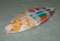
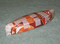
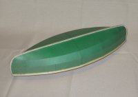
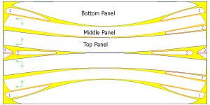
I was happy with the look of that boat,
at first. Then, after a while, a little detail bothered
me. Although the top and middle plank were ending
smoothly on the bow and stern, the bottom panel seemed
to have a bit of a bulge in that area. I didn't know
what to do next to correct that problem. I looked
back at my drawings, and eventually an idea emerged.
Looking at the end view, the chine angles used for
the midship section were equal:
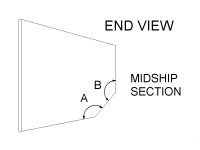 |
Chine
angles A and B are equal for the midship section |
What if the chine angles for each and
every station were equal? So far, they were not. The
difference in chine angle value just grew as you got
near the bow or stern. The drafting process had been
going a bit like this:
- Draw a midship section in the end view
- Draw a keel in the profile view
- Draw circle arcs for the sheer and chines
- Fit the stations to fit the sheer and chines
just drawn
-
With a twisted V-bottom, if I used
equal chine angles on all stations, the angle values
would be different for each station. The drafting
process would have to go a bit like this:
- Draw a midship section in the end view
- Draw a keel in the profile view
- Draw circle arcs for the sheer and top chine
only
- Draw lines for the bottom and middle planks
for one station
- Measure the chine angles
- Redraw until the top and bottom chine angles
are a close match
- Repeat for all other stations
Doable but tedious. I didn't have a
simple way of doing the task. I remembered a way to
draw a boat using circles I saw on a web page here.
I didn't know if that method could solve my problem.
It was based on an Excel spreadsheet, a program I
didn't have on my PC.
I played with circles and found a way
to use them that work, but not 100%. The last couple
stations still had to be done by trial and error.
Here is a pictorial description of how I did it.
 |
Click to enlarge |
Step
1- First, because the top plank is vertical
(mostly), the sheerline and top chine are drawn
in the plan view. The top segments for each
station can then be drawn. The area between
stations 0 and 2 is where the sheer, in the
plan view, changes from an arc to a straight
line. (Same thing between stations 14 and 16) |
 |
Click to enlarge |
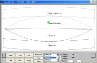
Step
2- Starting with the midship station (section
8), a circle (in blue) is drawn with 3 points
touching the top chine, bottom chine and the
lowest point on the keel. A copy of this circle
is placed with its center on the lower chine
point (dotted blue circle). A line (in blue),
placed at the edge of this second circle, is
drawn perpendicular to the bottom plank line.
Its length is delimited by the first blue circle.
Now, for a different hull shape, a different
position for that blue line would have to be
figured out. On the enlarged picture, red dots
show the circle's 3 points. |
 |
Click to enlarge |
Step
3- Section 7. A 3-point circle is drawn (in
green) with 2 points touching the extremities
of the blue line previously drawn and the third
point touching the top chine at this section. |
 |
Click to enlarge |
Step
4- Section 6. A circle is drawn (in orange)
in the same way as the previous circle. |
 |
Click to enlarge |
Step
5- Section 5. A circle is drawn (in turquoise)
in the same way as the previous circle. |
 |
Click to enlarge |
Step
6- Section 4. A circle is drawn (in yellow)
in the same way as the previous circle. |
 |
Click to enlarge |
Step
7- Section 3. A circle is drawn (in gray) in
the same way as the previous circle. |
 |
Click to enlarge |
Although
circles can be drawn (in brown and dark green)
for Section 1 and 2, the angle values achieved
for the top and bottom chines are no longer
close, probably due to the strong curve of the
stems. Those last 2 sections have to be done
by trial and error. |
One beauty of this "trick" is that
it automatically creates the curve for the keel. This
trick is still a work in progress: the 2 intersection
points for all circles were chosen by trial and error.
For a different hull shape, such as less deadrise
for the bottom, the position of those 2 points (the
ends of the blue line in this example) would be different.
A mathematician could probably perfect that trick,
but I am not one. What matters is that method worked
well enough to finish the last draft of my boat.
Did making the chine angles equal produce
a fair looking boat? I think so. As a bonus, this
new "rule" introduced just a little bit of hollow
in the lower chine, near the bow and stern. Although
the difference with the previous draft is subtle,
it definitely corrected the bulge problem on the bottom
plank. I now had a fine entry I was happy with.
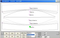
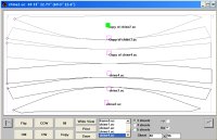
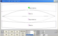
This is what the plywood sheet layout
looks like:
 |
Click
to enlarge
1.- Paddle (half)
2.- Paddle center plate
3.- Breasthook |
As you can see, there is not too much
waste. In fact, even the waste area (in yellow) will
be put to use. Splitting the paddle blades in half
allowed to squeeze them in. The only additional wood
required will be for the keel, inwales, outwales and
seat. Plus the temporary frame and backbone used during
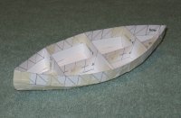
construction. Below is an illustration of the construction,
with the breasthooks removed to show more construction
details.
 |
Construction
(Click to enlarge) |
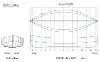
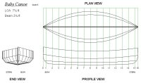
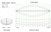
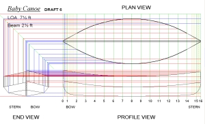
Here is a comparison between my design,
that I called Baby Canoe due to its diminutive size,
and a typical cruising canoe, according to W.P. Stephens.
| Dimensions |
Typical
Cruising Canoe |
Baby Canoe |
| LOA |
14 ft |
7-1/2 ft |
| Beam |
30 in. |
30-1/2 in. |
| Hull depth at bow |
18 in. * |
17-1/2 in. |
| Hull depth amidships |
12 in. * |
13-3/4 in. |
| Hull depth at stern |
16 in. * |
16-1/2 in. |
* Numbers obtained by adding Freeboard plus Draft |
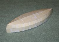
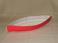
While I was approaching the end of
my drafting efforts, I finished reading an article
that was bad news for my design. According to that
article, a deadrise of 5 degrees is suitable for a
stable boat, 10 degrees being on the sporty side.
My design has 11 degrees. I knew that too much deadrise
would mean an unstable boat, I just didn't know how
much was too much. Now I knew. So I said to myself,
ah well, it's gonna be a tippy boat. If I wanted to
start building that year, it was too late to redesign.
The hull shape of my design would be best suited for
a keel boat perhaps, but my budget and space allowed
only for a canoe, so a canoe it is.
 |
According
to an article in this magazine, my boat will
be tippy, err, sporty. |
That's it for now. Stay tuned for the next part,
where we will begin construction.
On to Part
2

REFERENCES
SOFTWARE
|