| Click
here for Part 2
Part 1
In the rush to build as many prototype hulls as possible
this year; the completed FlyCaster was quickly removed
from it's place of honor on my building platform so
the two sheets of plywood for the PUD-g could replace
it. Building new hulls has become an obsession with
me this year, and building the PUD-g seems to have
reached a peak. I hope. It may slow down a bit, as
most of the hulls queued up are too long to fit in
my current work space. I will either need to add on
to the barn, or sell out and move down to the Texas
coast where I can build and use my 18ft cat ketch,
Raid design. Or go single hulling with my 15ft asymmetrical
hulled catamaran. Where was I?
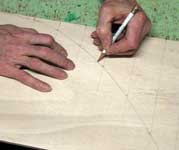
The layout of the hull panel outlines on the stacked
plywood sheets when very smoothly, with only a couple
of changes from the dimensions I had calculated off
the computer drawings. Mainly it was adjusting two
of the bow corner points so the "arc lengths"
of the two mating edges were within 1/8" of each
other. I had to use my layout batten, and measure
the distances pencil marked on some masking tape.
All my measuring tapes would cut the corners between
the brad nails and give me a false distance. I have
to get a cloth measuring tape and glue it to the batten
for use on other hulls. Once all the adjustments were
made, it was time to cut out the panels.
 |
|
It had been a while since I had worked with 4x8
sheets of plywood, and they looked so small compared
to the 5x10's I had been using on the last three hulls.
Moving the clamped pairs around on the work platform
was a lot easier. I was also chuckling to myself about
how small the panel pairs were after I had cut them
out and set aside; and kept asking myself if this
was really something to spend so much time on. Since
this PUD-g is not the same hull as the PDF
model you can download in my
area of the "Plan" section.
That PUD-g, wasn't. Once I think I am done with
the basic hull design, I print, glue, cut out, and
assemble the latest model; then hang it by a thread
over my kitchen counter where I eat all my meals.
I then spend days/weeks looking at it as the model
spins in any chance breezes that pass by. Or I just
blow at it. Sooner or later, some thing about the
hull just doesn't look right, and I give it a good
"eye balling". Turning it around in my hands
and wondering what's wrong with the hull, that it
makes me second guess what I have already done. This
time the hull just didn't look big enough. I didn't
really want to make any changes, because it was too
pretty now. But I know now that a small boat, (less
than 10ft) can not be really sleek and have the volume
to carry any kind of load. A small pretty boat is
actually just a scaled down version of what it should
be to do the job.
To prove to myself that I needed to make some major
changes, I laid out the hull outline on my kitchen
floor with bits of masking tape and then sat in the
middle of it. Yep, too small. Time to add some steroids
to PUD-g's diet. Now I get to spend even more hours
at the computer, then the making of seven more models
until I was happy with the design. Which meant throwing
away several pages of completed detail drawings. :(
But as a confirmed scab scratcher, I had to do it.
Nobody is going to be more critical of my designs
than me. No one! This pudgier PUD-g is not as pretty
as the first, but can more than stand up to the demands
placed on it, and still be true to the "mission
statement" that I set out with when I first though
of designing this hull. (see the cover letter
on the PUD-g
in my plans area)
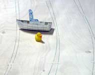
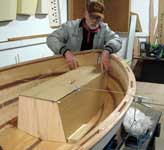
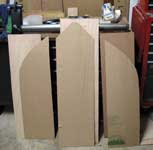
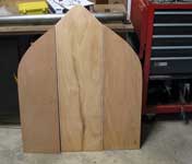
With the hull panels all cut out, it was time for
the "outside" photo. I was still wondering
what the heck I was doing when I saw the photo, but
that changed to fatherly love when I had the panels
all wired together. Like babies, kittens, and puppies,
something about miniatures brings out a protective
instinct, and an obsession to nurture. It became necessary
to force myself not to work on the boat and live "my"
life. Even as I write this I am way behind on the
plan drawings and updating the text instructions;
and the hull is 90% complete.
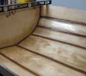
Hull assembly when smoothly, with no problems. I
did find a couple of flat spots along the hull seams,
but some 1/8" shims fixed those. I wasn't sure
if it was from the design or cutting out the panels.
Judging from their locations, it had to be me moving
slightly inside the line as I cut. No big deal. GelMagic
and EZ-Fillet
can cure all my mistakes.
 |
|
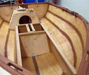
With the PUD-g, I wanted to make a pure "deck"
boat in the ongoing wars over hard-shell or inflatable
tenders. As a ships tender, I wanted a strong workable
solution, that was 100% practical. No extra fancies
on the interior, and lots of secondary flotation in
case of a breaking wave on a beach landing. I also
needed room for people and their supplies. As a seakayaker,
I knew the benefits of watertight storage compartments,
and the extra flotation they have built in. As a whitewater
canoeist, I know of the added safety that buoyancy/displacement
air bags give in keeping you and the canoe on the
surface in big water. With that insight, I made the
interior seating on the PUD-g part of the hull, with
storage, and reserve flotation.
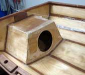
On the Laura Bay, I had boxed in the area around
the daggerboard case to use as extra flotation. I
now wished I had added a 4" quarter turn hatch
to each side in the plans. I will do this to my own
hull later. On the PUD-g, I have added the four inch
hatches, plus two six inch hatches on either side,
of the forward seat compartment. If you so chose,
you can add an extra bulkhead to divide it again.
Just offset one hatch forward of the other. That forward
hatch may be reduced to a four inch model to fit better.
The stern seat box is wider than the main center seat,
and is fitted with a larger eight inch hatch. All
the seat panel to hull seams are filleted with EZ-Fillet,
and a layer of 2" glass tape on the outside.
World cruisers can add a fillet to the inside seams
if you chose to do so for added strength.
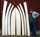
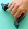
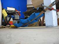
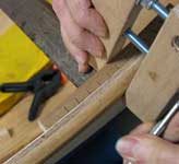
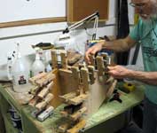
Because of the heavy curvature near the bow with
this design; I have gone to the "spaced rail"
gunnel system. All the rail parts are ½"
x ¾", ripped out of Philippine Mahogany.
Once I have ripped out the rail stock, they are stacked
into two pairs. Port and starboard, with the "inner"
rail on top, to form to it's mate. The bow ends are
tied together and raised at least 18" off the
floor. The stern ends are raised about 8" off
the floor. I added some loosely tied cord at three
places along their length to keep them together, but
able to slip independently. I then placed some sandbags
on the rails, and closer to the bow end to induce
curvature. More bags are added and moved closer to
the bow end over several days as the wood takes a
set. You could also do this by making up a jig out
of an eight foot 2x4 with the two risers nailed at
each end. Then the rails could be tied to the jig,
and forced into a curve over several places. You do
not want any "point" loads. A light spraying
of water at the start can help too. The rails need
to be kept this way for a week or more to take on
a set and keep from "snapping" when you
go to install them.
 |
|
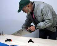
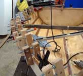
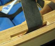
Another problem I encountered was fitting the spacer
blocks to the heavy curvature. I didn't want to put
excessive pressure on the hull panel and the outer
rail by just applying massive clamping pressure to
make the spacer block conform to the hull. To get
around this, I placed "relief" cuts on the
outer side of the spacer blocks; and this let them
easily flex to fit the curve of the hull. I only had
to do this at the #2-3-4-5 station lines. The other
blocks glued up with no problems. I did change the
block spacing in the plans drawings, from what I used
on the prototype hull, after rethinking the spacing
pattern. The new scheme is a better fit.
 |
|
| 
|
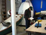
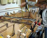
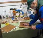
With every new hull prototype, I spend a lot of
time thinking about seat height, and how to make sure
that measurement will remain the same from bow to
stern. Half the battle is making sure the hull is
sitting (to what I think it will be) on it's lines.
Serious head scratching, but I am usually on my (it's)
mark. With that information, I then set up a (rubegoldberg)
series of strings and scrap sticks to project that
idea to the hull. Then I go about measuring all the
heights and widths for the various parts that make
up the seat and daggerboard assemblies. After a few
cardboard cutout mockups, I can then mark and cut
out the plywood pieces. Sometimes they become backing
plates for future projects, and I go scrounging around
the shop looking for more bits leftover from previous
hulls.
 |
|
| 
|
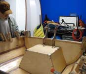
The stern seat assembly went together smoothly,
with a couple of adjustments to the bottom edges of
the panels to fit the hull. The whole assembly was
jump stitched, filleted, and glass taped on the inside
before I attached it to the hull. With 6mm plywood
backing plates for the top seat panel, and for the
8" hatch area. I also added a layer of 6mm ply,
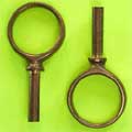
and a piece of ¾" x 1" rail material,
to the inside of the stern panel to give extra support
to the area where the rudder gudgeons
are mounted. The rail material and the set assembly
had to be relieved to fit this addition.
In order to judge how the "main" seat
assembly would go together, I had finish the daggerboard
case. The PUD-g is using a NACA 0010-8" cord
daggerboard. So I needed to figure out and design
the shape, find the overall width of the foil, and
then determine the case's open length and width to
have room for the daggerboard to "gybe"
inside it. Once that was done, I could cut and assemble
the case.
 |
|
 |
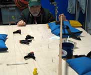
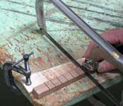
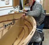
One of the things I remembered to do this time,
was to measure and mark a line 2" offset from
the keel line seam. On my other hulls, the filleting
and glass tape layers hid it's true location and I
had to crawl under the hulls, and drill a pilot hole
up from the bottom. With this line, I was able to
reestablish the true keel seam and mark on masking
tape that location. From my half model CE/CLR locations,
I knew where the aft side of the DB case would go.
Out comes the centerline cord and the "pencil
bobs". After making sure the hull was still level
on the work platform, I centered and aligned the DB
case, and held it in place with a weight. More sticks
to determine where the main seat would meet the bow,
and a couple bits of masking tape for that location.
Now the fun part of figuring out how the main seat
side panels would be shaped and fit to the hull. More
cardboard, mark, cut, mark, cut, mark; you get the
idea. Once I had a shape that seemed to fit, I tried
it out on the other side. Close enough for EZ-Fillet.
With them taped in place, the top seat panel was cut
out of cardboard and everything was taped together
to see if it worked. I then took some measurements
off the cardboard mockups and projected those figures
onto the plywood as a check for me and my numbers.
Then a test of faith when I cut out the plywood panels
to those measurements. There was some reshaping to
the bottom edges before finally epoxying them in place.
All hulls will have to have some reshaping due to
the variability's of construction.
 |
|
 |
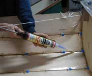
With all the parts cut and shaped, it was time to
start making things permanent. The daggerboard opening
in the hull was located and marked with some pilot
holes. I do the cutout when the hull is upside-down
getting it's bottom glassed. The DB case is located,
jump stitched, then EZ-Filleted and glass taped in
place. The main seat top and side panels have their
backing plates attached with epoxy or GelMagic;
and the hatch openings located and made. Everything
is then coated on all the inside panel faces and edges
with two coats of epoxy. The main seat side panels
are then attached to the DB case with some stainless
pilot screws to maintain alignment, and a thick layer
of GelMagic on all the mating surfaces. The top front
width of the side panels is checked and held in place
with a bit of scrap and clamps or screws. The side
panel to hull seams are jump stitched and everything
is left to cure.
The mast step/partner assembly on the PUD-g is a
bit different than on my other boats. I haven't finished
with it yet, so this is a good place to stop for the
time being. To see a lot more photos of the construction
process to date for the PUD-g; go to the following
link. I will be adding photos until/after the plans
are ready for sale. www.flickr.com/photos/pud_g
 |
Click the image
at left to download a printable paper hull model
of the PUD-g |
Thanks again for reading my stories. I look forward
to your comments.
Warren Messer
Red Barn Boats
Click
here to proceed to Part 2
Plans
and study plans for PUD-g available here

Other Articles by Warren Messer
|