| ... to Prevent Propellor
Ventilation
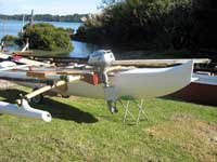
Attaching an outboard motor to almost any type of
double ended hull generally involves using a bracket
mounted on the side of the hull. Some small catamarans
also have their outboards mounted to a bracket between
the hulls. Without a transom or deep fairing in front
of the leg of the motor, severe ventilation of the
propeller can occur and reduce the thrust of the motor.
Ventilation (where air is sucked down into the propeller)
occurs because of the turbulence behind the leg of
the outboard motor.
The two horsepower motors are the worst offenders,
with an almost round leg between the power head and
the anti-ventilation plate. Larger engines have a
more streamlined leg shape and don’t have as
much of a problem as the two horsepower size. Unfortunately
for me, the outrigger canoes and proas that I build
don’t need any more than two horsepower, so
a solution was needed. The new Honda two horsepower
motor, that I had recently purchased, ventilated horribly
at any speed more than an idle, and threw large amounts
of spray into the aft section of the canoe.
I decided to fabricate a fairing around the leg of
the motor to reduce the turbulence and hopefully increase
the thrust. I considered many possible methods and
materials, and I didn’t want something that
would be too difficult to remove if it didn’t
work as I expected. Flat panels of fiberglass bent
around the leg in a foil shape seemed to be the easiest
solution. Sheet metal could also do the job, but my
workshop was better equipped to make it out of fiberglass.
I fabricated a flat panel of fiberglass,
using a sheet of window glass for a mold. I applied
a coat of mold release, allowed it to dry, and brushed
on some gray polyester gelcoat. After the gelcoat
had set up, I saturated a scrap piece of 18 ounce
biaxial fibreglass fabric with vinylester resin on
top of the gelcoat. Three or four layers of 6 ounce
woven cloth could also be used. The next day, I peeled
the fibreglass panel off of the sheet of window glass.
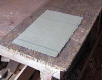 |
I fabricated
a flat panel of fiberglass, using a sheet of
window glass for a mold. |
I used a jigsaw with a carbide grit blade to cut
two identical rectangles from the panel. The two rectangles
were taped together along the future leading edge,
and opened in a vee shape held at a 70 degree angle
by a couple of foam wedges. A small fillet of vinylester
resin and glue powder was applied along the inside
of the joint, followed by two strips of six ounce
fibreglass cloth.
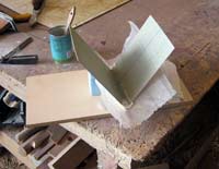 |
Two rectangles
were taped together along the future leading
edge, and opened in a vee shape held at a 70
degree angle by a couple of foam wedges. |
The next day I tested the fit by bending the vee
panel around the leg of the motor, with the bottom
edge of the panels resting on the top of the anti-ventilation
plate. I was pleased with the curved shape and decided
to go ahead with bonding it to the leg. I applied
packaging tape along one trailing edge of the panel
with the tape overhanging to allow it to hold the
two panels together when bent around the leg. I applied
a bead of silicone sealant down each side of the leg,
and a generous bead of resin/glue powder mixture along
the inside of one trailing edge. I folded the panel
around the leg, and wrapped the tape over the trailing
edge. So far so good and it didn’t spring loose
and fly across the shop.
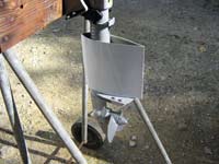 |
I folded the
panel around the leg, and wrapped the tape over
the trailing edge. So far so good and it didn’t
spring loose and fly across the shop. |
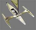
The next day I couldn’t wait any longer to
test it, so I clamped it to my Ulua outrigger canoe,
loaded up some fishing tackle, and headed out across
the harbor. It performed beyond my expectations, with
no ventilation occurring at any speed. Normally with
side mounted installations, a hard abrupt turn can
also cause some ventilation and over revving, but
this little problem was cured too. At this stage the
foil had no top panel, and a thin sheet of water was
peeling off the top edge. An over-size top panel or
fence would deflect the water outwards and also stiffen
the whole foil installation. I laminated another flat
fibreglass panel at twice the previous thickness,
cut it about 5/8” larger all around the foil,
and bonded it (in two pieces) to the top of the foil
with a resin/glue powder fillet.
It’s important to be able to rinse out any
salt water from the inside of the foil to avoid any
corrosion of the leg, so I drilled two holes in the
top panel. The two bottom corners of the foil already
had small openings for drainage where they overhang
the anti-ventilation plate.
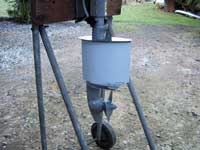 |
The next day
I headed out across the harbor. It performed
beyond my expectations |
I choose the Honda engine because it’s a four
stroke, it’s air cooled, and it has a centrifugal
clutch, but the clutch can cause a small problem when
approaching the shore or a dock. If you use the motor
to steer (rather than a rudder), reducing the throttle
to slow stops the propeller turning, and you lose
steering control. An unexpected benefit of the large
foil around the leg is that it functions as a rudder
after the propeller has stopped.
If I ever have to remove the lower unit from the
motor, I’ll have to cut a small hole in the
fairing to access one of the bolts, but since that
shouldn’t happen very often (no water pump!),
a simple patch job will restore it to its former shape.
Ideally this fairing could be made of some high
density foam in two halves, so that it could all be
removed with a couple of screws. There is exhaust
flowing in the leg though, so maybe having cool water
around it is best.
 |
An unexpected
benefit of the large foil around the leg is
that it functions as a rudder after the propeller
has stopped. |
gary.dierking@gmail.com
https://gary.dierking.net

|