| To Part One
Circuit Analysis
I assume you skimmed the above section. Before you give yourself a headache, remember that you do not necessarily have to do it! The only reason I need to understand this circuit at all is that I could not positively identify some of the parts. If you get clear part numbers from everything, you can simply build an exact replacement.
Another approach would be to build a CDI box following the plans by John Clarke in an Australian magazine called Silicon Chip (https://siliconchip.com.au/cms/A_110499/article.html). It looks fairly similar to this circuit, but has some cool additions like temperature compensation. Maybe this doesn’t matter so much on a snowmobile, but it is a cheap addition I would consider for an outboard.
Unfortunately, Mr. Clark’s circuit is for motors that fire on the positive part of the trigger pulse. The diode leading to our trigger coil points the wrong direction for this, so it must be designed to trigger on the negative half. I wired up Mr. Clark’s circuit just in case, but the best I could get was one spark and then nothing. Oh well.
By now any sane person would have decided Max is right and points are simpler. Did I? Um…
Back to the circuit analysis.
How Coils Work
First let’s talk about the coil. Physically it is a core made out of layers of iron, with a couple windings of copper wire around it. In this case the secondary winding had many more turns that the primary. This structure is also called a transformer when used to change the voltage of AC power.
In this application, the spark is created when electricity is cut off to the coil. How? When direct current runs through the coil’s primary, it turns the iron core into an electromagnet, but it doesn’t induce any current in the secondary. Only changing voltage in primary induces current in the secondary. This is why transformers can change the voltage of AC power but not DC.
The faster you change the primary voltage, the higher the voltage induced in the secondary. This is why your TV uses high frequencies to get away a small transformer, but an old tube amp weighs a ton because of all the iron and copper needed to transform 60 Hz (low frequency, thus changing slower).
Back in our ignition coil, as the magnetic field collapses in the core, a voltage is induced in the secondary. The faster the field collapses, the bigger the voltage. When the field collapses really fast, this spike has enough voltage to arc across the spark plug terminals.
Coil Switching Circuit
The only difference among ignitions systems is how we cause the coil’s primary to discharge fast. Mechanical breaker points do this job by breaking the circuit to the coil, which shuts off power to the coil primary. Then, of course, the magnetic field collapses and we get a voltage spike in the secondary. Here we do it the other way around. The capacitor gets charged relatively slowly by the high voltage coil on the flywheel, and the coil primary gets charged along with it. Then the trigger coil turns on an SCR (making a connection rather than breaking), which drains the capacitor almost instantaneously, much like in a camera’s flash unit. This also discharges the coil’s primary and the spark is formed the same way from there.
Thus, the only real difference is that the CDI system discharges faster than the breaker point, so we get a hotter but shorter spark. Generally these are good things in a two-stroke engine.
Let’s take a walk through this cycle in our circuit.
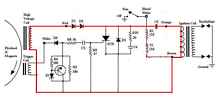
First the magnet swings past the high voltage coil, charging the capacitor. Notice that there is current going through the ignition coil primary, but the change is not fast enough to induce in the secondary a jolt big enough to make a spark. I traced the current in red for this first step. This exciter coil will produce both a positive and negative voltage bump. We only want the positive, so D3 shorts out the negative part. I think R10 and C4 are mostly to short out high frequency noise that can cause false sparks.
We can pretty much ignore R1 and S1. They are such high values they don’t affect the circuit much. They are only there to drain the capacitor so you don’t get shocked working on the motor. It takes a few seconds for the capacitor to drain, which is way too slow to come into play while the engine is running. If the capacitor is a holding tank, these resistors are like a tiny leak in it, to drain it after you shut off the water supply.
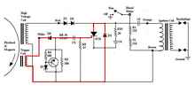
So now we have a charged up capacitor. Then the flywheel magnet passes the trigger coil. It generates the pulse that turns on the SCR. I had thought the SCR’s gate needed to go positive with respect to the cathode to turn on, but apparently a negative pulse will also do the job. However a negative pulse needs to be bigger than if it were positive. (Thanks to Mr. Clarke for pointing this out to me.)
Once the SCR turns on it drains C5 to ground, and keeps conducting until it is drained. This of course causes the magnetic field in the transformer to collapse, causing the voltage spike in the secondary, and thus our spark.
That leaves the small circuit with the unknown zener diode and transistor. But I’m running rather long, so we’d better get to that next time!
We still need to figure out how that zener circuit works.
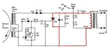
Zener circuit
Since we are dealing with high voltages, I’m guessing that the transistor is there to allow us to use the effect of a small, cheap zener diode at voltages beyond what it can tolerate. This approach is discussed here: https://sound.westhost.com/appnotes/an007.htm
Essentially I think the zener diode circuit is there to chop off the highest voltages from the trigger coil, so they don’t fry the gate of the SCR. Theoretically you could find a really high voltage zener diode to do this and put it in parallel with R5. So you start out with a 180 ohm resistance. Once the zener diode sees a voltage higher than its zener voltage, it shorts the excess current. You can see why these are used in regulated power supplies.
The trouble is that zener diodes are not cheap or common in high voltages. Transistors are. So this little circuit lets a transistor take the beating of the high voltages, and uses the zener to tell it when to turn on. Clever. With two 180 ohm resistors in parallel, the zener diode only sees half of the total voltage for this part of the circuit. Thinking in plumbing terms, when you have two pipes the same size, they both get the same amount of water. (Some of the pulse also goes through R8, R9 and C3, which further reduces the stress on the zener. We won’t do that math here.)
Once the zener circuit sees more than twice the zener voltage, the diode opens up. This allows the base of the transistor to be charged, which turns it on. The transistor goes to a very low resistance then and conducts most of the power in the trigger circuit. The much higher resistances of 180 ohms (and also R8, R9 and C3) will get hardly any juice at this point. But as soon as the zener diode again sees a voltage less than its zener voltage, it stops conducting and thus shuts off the transistor.
So let’s use that to make some guesses on parts. Basically we want enough gate current to reliably turn the SCR on at all RPM settings, but not so much we heat it up destructively. There is probably a fairly wide range available to us, so we can probably experiment our way there. But let’s try to get in the right ballpark.
I would love to do some engineering and figure out what parts we need here, but the manufacturer of the SCR doesn’t mention how much negative pulse we need to turn this thing on. So I guess we need to determine it experimentally.
Zener Experiments
But before we start testing what the SCR will and will not respond to, maybe we can take a shortcut. We already basically know the circuit topology, so let’s try running this thing changing the values we’re unsure of.
Let’s start with a transistor that can handle 200 volts and maybe half an amp. I went with a high voltage, high speed transistor (ST130009), simply because other components in the circuit are listed as such. It is probably radical overkill, but I can be pretty sure it won’t blow up. Since I’m only making one or two I don’t need to worry about putting in a $1.50 component where a $0.07 part would do. It also helps me get around the fact that my component choices here are guesses!
Let’s also try a zener diode with a 3.3v reverse breakdown voltage. This isn’t even a guess – I just had some on hand. Now let’s wire up the circuit, but in place of the 180 ohm resistor feeding the zener, let’s use a variable resistor. You’ll find those listed as potentiometers or rheostats. I used an old one I had laying around that used to be in an amplifier, but they are only about $1.40 new.
The idea here is that we sweep the resistance until the circuit works like it should. The safe way is to start with a lot of resistance protecting the zener diode, then work down into less resistance until we get a reliable spark.
The cool thing about this is that it can help us adjust for a zener with the wrong voltage for the circuit. The original had two equal 180 ohm resistors, as the zener’s cutoff was perfect for half of the required cutoff voltage. If ours isn’t right at half, we change the resistance so the zener sees something other than half.
While this approach makes a lot of sense, it didn’t work. Something else was wrong. Time to pull out the secret weapon.
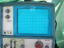
The Oscilloscope
I resisted using this tool because I know most of you don’t have one. I got this one on Ebay for like $75 plus another $20 in probes. This is absolutely dirt cheap for a decent brand (Tektronics) dual trace oscilloscope that works. There’s a lot of junk out there, so caveat emptor. Better yet, make friends with some amateur radio guys who have oscilloscopes! With as seldom as I use it, this probably would have been the smarter approach for me too.
The beauty of this tool is that it lets us see what’s going on with electricity. Basically it gives us a graph of voltage against time. A good primer can be found here: https://www.tone-lizard.com/Oscilloscopes.htm.
First let’s see if the exciter and trigger coils are even doing what they are supposed to. Start on a really high range for this, because the voltage can spike really high with no load to drain it away.
I tried every trick I could think of to get a screen shot of the scope, but my camera was simply not equal to the task. Especially because I was yanking the struggle string at the same time! So here are my approximate drawings of what the traces on the screen looked like.
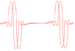
[Does not enlarge] |
I didn’t show you the divisions, but we’re set at 100 volts per division, so we can tell we have swings of about 300 volts positive and negative. This is at .1 ms per division, so I’m turning the motor at around 120 rpms with no sparkplugs in.
But this is really weird. One would not expect the two coils to be sending nearly identical signals! After all, why have two coils and two wires if you’re going to do that? I would think we’d see a big, slow buildup for the charging coil, and a small, quick pulse for the trigger coil. Something could be wrong here. Perhaps a short. Or maybe they just use two similar coils because it’s cheaper.
Worse, when I plugged in my circuit and tested it, I had no signal at all to the gate of the SCR. Well, there’s the problem. I could get a little pulse at the trigger coil’s input, but after that first diode it was gone. I guess my zener circuit is killing the signal. This was true no matter where I set the potentiometer. So let’s remove the zener circuit and see what happens.
With the zener circuit removed, we see a sawtooth wave when measuring from anode to cathode on the SCR. This represents charging and discharging of the small capacitor in parallel with the SCR, I think.
Measuring voltage across the big capacitor we see that it charges up and then slowly discharges though the two 1 meg resistors. On the scope this looks like the line staying flat but going high, then drifting slowly back to where it started.
But still no luck with the trigger signal. The trigger signal is getting shorted by something else. I disconnected the resistor to ground, which didn’t change anything. When I cut disconnected the trigger signal from the SCR, it came back! The SCR itself was shorting the trigger signal! Something is very weird here, and I’m beginning to suspect that SCR isn’t a “normal” SCR, but rather is some special component. Or perhaps I have the pinout wrong.
Sanity Makes an Entrance
About this time my wife informed me that I had spent more than enough time on this project, and that it was over. (I left out the parts about designing and etching circuit boards!) She’s usually right about these things, so I gave the sled away to the first willing party.
Here what really caught my notice in retrospect: A motor with a totally shot points ignition would have been like new after three hours and $25. I went through three months, at least $25 in electronic components, who knows how many hours, and needed an oscilloscope even to figure out that I didn’t know what I was doing. Solid state electronics can really soak up some development time, where with points…well, you can tell if they’re bad by looking at them!
I guess this tour of electrical theory tells us a bit about how ignitions work, which is good. It also tells us a bit about which projects to avoid, which might be better.
And it tells us Max is right! I guess I’d better re-read his book.
Rob Rohde-Szudy
*****

|