I was pleased to discover the nine articles that the late Barend Migchelsen wrote in 2001-2003 which discuss the mathematics used to define a boat's shape. They are found here in Duckworks in the 2001, 2002, and 2003 issues. Article 7 is titled 'Dutch Punters"; the rest are titled "Boatbuilding With A Difference". (see links at bottom of this page)
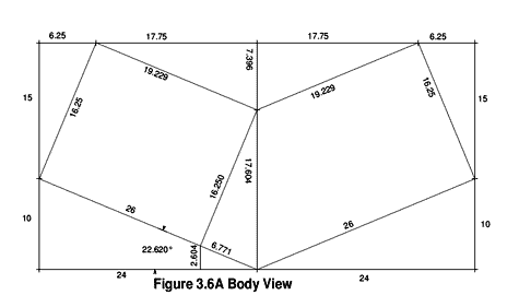
While every necessary formula can be found, the information is not well-organized. It will be easier to understand if you start with article 9 first. Article 1 is based on a boat that has a 48" beam and has a 16' OAL, but no other data is given; you will eventually stumble across it in figure 3-6A. With that figure in hand, articles 1 and 2 can be understood.
click image above for PDF version
In some cases, the word processor used to write the articles did not handle mathematical symbols very well (neither does my Word for Windows). Most of them can be deciphered quite easily, but the one in article 3 about "SAC (Stem At Chine)" to find dSAC made no sense. I finally figured out the formula was:
hSAC + (R-hBeam) = SQRT(R2 - dSAC2)
which, when solving for dSAC, becomes
dSAC2 = R2 - (hSAC+ (R-hBeam))2
Likewise, under "Offset Table...", the formula is
hn = (SQRT(R2 -dn2))-(R-hBm)
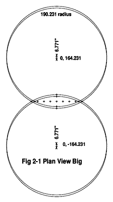
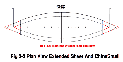
Article 2 starts by explaining that the Plan View is the "Seagulls' view. In the Plan View, the chine and sheer are parallel circles. The seagull sees ellipses which are not parallel. Maybe it should be called the "fishes' view"?
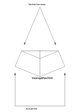
Viewing a Plan View
click image above for PDF version
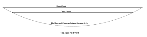
The Real Fish View
click image above for PDF version
Nonetheless, the Plan View makes all the math easier to visualize.
click image above for PDF version
click image above for PDF version
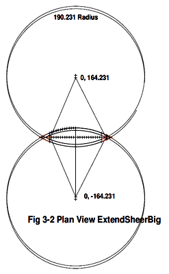
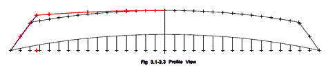
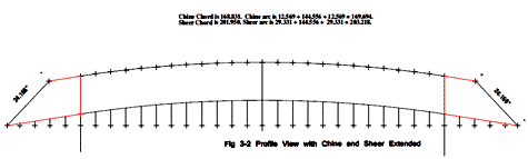
Article 3's formulas did not work until I finally noted that figure 3.1, 3.4 and 3.5 used a different boat as shown in figure 3.3. The example using figure 3.2 probably should explain that the chine also needs to be extended from station 24" using the same angle.
click image above for PDF version
click image above for PDF version
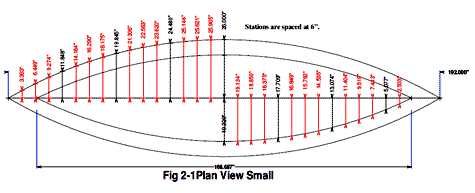
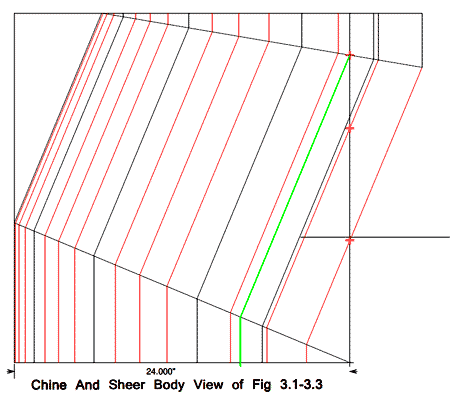
The articles use only the stations with 24" spacing; in most cases that is accurate enough, but as you can see in the body view of figures 3.1-3.3, a 6" spacing was used, and you can use other spacings if you wish.
click image above for PDF version
click image above for PDF version
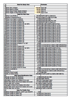
Article 5 insists that it is easier to loft the boat full-size rather than using an expensive computer and software. Maybe so, but most people do not have room for a 16 foot wooden floor, and my Visual Cadd measures more accurately than I could with a compass. Once I have drawn the boat, I can easily print the panels to make a scale model to find any mistakes. Eventually I figured out that an Excel spreadsheet could do all of the calculations if I could input the right formula! The answers it outputs and the formulas can be seen in the attached figures. I apologize that some of the names are not very descriptive; that is why I printed the formulas to the right of the answers. And, yes, I know that there is no need for three-decimal place answers, so feel free to round-off to the nearest 1/6th".
click image above for PDF version
Note that the spreadsheet is two pages. Also please note the .XLS file is available for download also.

click image above to download .xls file
Figures 3.1, 3.4, and 3.5 show how to change the rake of the bottom if desired. I drew some of the profile change that results.
click image above for PDF version
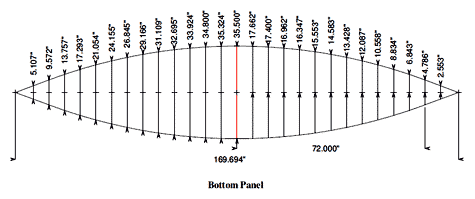
The only thing I could not figure out was the length of the bottom panel. The profile view gives the chord of the arc, but I could find nothing for the length. I finally used Visual Cadd to draw a spline curve to connect the points which were at 6"intervals and then had it calculate the length of the arc between each point. The end result was accurate, as the length of the side arc of the bottom came out within a few thousands of the length of the side's chine. Please note that the widths calculated in Excel do NOT exactly match those in the bottom panel figure. The reason is that I redrew the stations back to 6" intervals on the bottom view. Eventually it occurred to me that the curve of the profile might be close to a circle. I found that the length of the arc of a circle that touched the midpoint and the ends of the rake curve was identical to what I had calculated with Visual Cadd. I added the formula for finding the circle at the end of the Excel spreadsheet. It is possible that Excel can find the real spacing between the 6" stations and the real length of the bottom, but that will have to wait for another day. If anybody knows of other ways to find the length of the bottom, please let me know.
click image above for PDF version
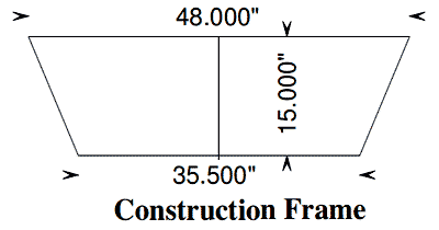
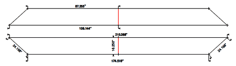
Will all this math make a boat? I made the panel drawings for the sides, bottom, and a construction frame (the red lines on all 4 items should line up).
click image above for PDF version
click image above for PDF version
click image above for PDF version
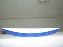
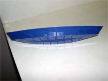
I printed the panes at 1/16th scale and glued the paper to poster board, cut out the pieces, and scotch-taped them together. I could see no place which did not fit as it should. Above are pictures of the model.
I have not yet attempted to make boats of other shapes, but I think the drawings I have of the double-pointed boat can be easily modified to yield panels which fit together accurately. I hope this article can help others to understand what Barend Migchelsen was telling us.
By the way, the answer to his brainteaser in article 5 is "E"!
Links to Barend's Original 9 Boatbuilding articles:
Other articles by Barend Migchelsen:
*****

|