| To Part One
To Part Three
Part Two of Three
Her Build
The plans from John never really arrived due to an apparent glitch in the need to print plans in the middle of the New Zealand summer where attention to pesky business often gets bumped for the far greater need of respite and cooling libations... however, to be fair, I did received a PDF file that could be printed for the full set of construction plans with costs being ameliorated by having the privilege of keeping the plans for the "Navigator" which had been sent to me much to the chagrin of someone in Europe who most likely received the "Pathfinder" plans rather than the "Navigator"..( John's theory .. ). All was well, except when printed, the plans were a slightly smaller scale that the 1:10 needed if one was to scale directly from the plans for various pieces that were not dimensioned on paper... time for the professional background to kick in and just get on with it....
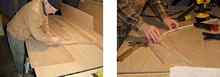
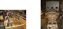
Much of the building plan was followed during the course of frame construction, stem, centreboard, rudder etc. to the point of set up on the strongback. Frames of ¼ inch Aquatek marine ply, floors, bulkheads etc of 3/8 and the bottom of ½ inch. The centreboard was a bit work, stacking the laminates of oak and fairing to a reasonable foil. I went for a little more lift than shown on the plans as 'flatter' bottom sailors (especially in smaller sizes) tend to make more leeway than larger boats that have a larger 'bite' on the water unless the design is exclusively for racing.
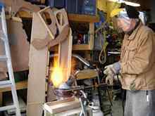
The frames were all struck out and assembled and stacked ready for set-up while work continued on the transom, stem, and centreboard and trunk and the long, scarfed bottom panel. As the centreboard required some 40 + lbs of ballast, a 45 lb cannonball from our retired troller was tossed in to a pot, toasted with a tiger torch, poured into a rectangular box that would fit snugly into the cavity cut out in the lower end of the centreboard. The lead slug was dimensioned so as to be able to split the cut-out piece and epoxy the two halves either side to enclose the lead ballast, to be faired flush with the rest of the centreboard.
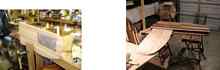
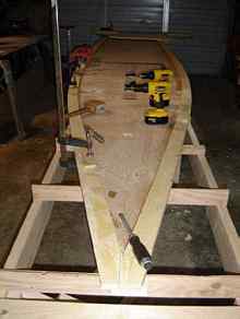
The strongback had been left to this point of construction as there was enough room in the shop to not need it as a 'workbench' for the frames etc. The large bottom panel was scarfed and layed to it's profile curve with blocking from the horizontal strongback. The cleats on the outboard sides of the bottom panel proved to be a bit of a challenge in bending them to the curvature dictated by the panel due to their designed scantlings but with adequate clamps and judicious placing of the scarf joints, they were muscled into place and secured with epoxy and 10 x 1 screws.
Now came the quick, fun part of the set-up. With all the bits and pieces of the framework waiting patiently on the sidelines, they were soon temporarily in place on the bottom panel and sighting checks were made to see if the dimensions so carefully laid out frame by frame actually faired nicely with each other. Compliments to the designer and the "offsets man" who picked those dimensions from the original lines plan; all was within reason with a tweak here and there. The only noticeable 'wump' was the framing that provided the motor mount that had a 7 degree tilt aft by design; despite assurances that it's shape had been 'developed' to compensate for it aft leaning disposition, it was obvious that is was not - temporarily laying in the stringers indicated a pronounced 'bulge' which was subsequently faired out by reducing the frame's girth..
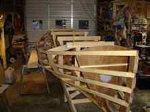
Once the frames, stringers and other various other pre-fabricated pieces were permanently in place on the bottom panel, it was time to contemplate planking. The plans and 'suggested' methodology was to plank her as she sat upright on the strongback. Hmmmm... as there would be a reasonable amount of fairing on the stringers to match the laps of the plank, including the cleats on the outboard of the bottom panel, rolling her over began to make a whole lot of sense, provided not a whole lot of stress was placed locally on any one spot of the framework. This would also entail an additional temporary structure on which to sit the framework as the planking proceeded. A decision well made.
A few 2 x 4's, some diagonal bracing athwart ships and fore and aft, two large inflatable air bags (the kind kids use to jump off the roof of the house and bounce around like human jelly beans.) and over she went.
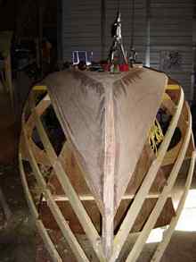
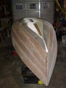
The planking proceeded in an orderly fashion from the 'bottom' down, the first plank certainly presenting the greatest challenge when fitting in the bow area. The 8mm marine ply from Aquatek put up a damn good fight to avoid distortion despite the stem being cut back a bit at the forefoot but slowly but surely, with the appropriate progressive clamping and 10 x 1 fasteners, it was drawn into place amidst the odd creak and groan. I could only imagine trying this lying on your back beneath a 'right side up' framework; again, a decision well made.( I've only cursed John a few times so far..)
A layer of 6 oz glass set in West System Epoxy, was laid over the bottom panel and partway up the first plank( in anticipation of taking a few beaches here and there to unload camping gear before springing her back out to anchor).
To be continued...
 |