| To Part Two
Late in 2010 Michael bought plans for the Ultra Pram, an all purpose transportable, ideally suited for small family boating because of its excellent freeboard and safety buoyancy compartments. This was to be Michael's first time at boat building, and he chose this design because of its potential simplicity. The first thing he noticed is that the plans were in standard US measurements, that is, feet and inches. Michael contacted me (e-mail) and asked if they were available in Metric dimensioning, and I responded negatively, but said I would convert them for him and send the new plans in a few days. Within a week the metric plans were in his hands, ready to begin the construction process.
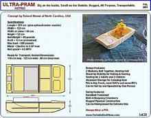
Ultra-Pram Plans Cover Page |
Initially, some terminology on the plans needed explanation, and we worked this out over a couple of emails. One important thing was the available material sizes in Australia. Although similar to the US, clarification was required. The plans call for building the rear module first, as it is a simpler build, with straight sides. As he read through the plans however, he determined that he would start construction on the forward module first, as this took up the least working floor space, for which he had little at the time. That may have been a beginners error. Initially things went along pretty smoothly, with an occasional question here and there, but progress was being made. Then things began to unravel.
It seems that in my haste to get the metric plans to him, I made some incorrect conversions, and a few dimensions did not produce panels that fit together properly! Needless to say I was devastated, as I knew this would be wasting the good plywood that he had purchased. I quickly made the necessary dimensional changes and he was able to reclaim some of the mis-cut plywood. A couple of other faulty dimensions reared their ugly head, and more corrections were made. This time Michael caught them prior to cutting.
|
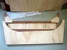
Center Bulkheads Complete with Safety Bolt Gussets |
Each phase of the build Michael would send me photos to insure all looked OK to me, and many of these are included here for the reader to appreciate. I have captioned them for clarity. I must say, for a first time builder, Michael has done some very nice work. The cuts are clean and straight where required, and the panels all fit together properly with no twist or misalignment. The end result should be very pleasing to him.
|
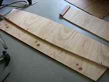
Bent Wood and Nail Method of Marking the Bow Radius |
Below is an excerpt from one of his e-mails .
Jan 05,2011
Hi Ken
Hope you don't mind but I have more questions. As you might have realized I am a novice at this!
I am at the construction stage and following your steps. Step 1 states assemble upside down. As there is an angle to the tops of the centre bulkhead I noticed that the side panels do not sit flush to the building surface (concrete garage floor in my case), the sides need to be raised to stop any sagging and misalignment. Would it be better to assemble the right way up? Or place a suitable wedge (left over ply) under the sides.
As I read through the complete assembly instructions I noted the final step 35 is to attach the filler blocks and gussets. Would it be acceptable to attach these at step 1? I think this would be easier than doing it when the sides and floor are in place.
Thanks again
Michael
And my reply:
Hi Michael,
No problem. You could turn the whole thing over, right-way up as you say. Perhaps easier for most.
Otherwise, a wedge should be used to maintain proper side panel height.
As for the filler blocks and gussets, they can be added at any time. They are at the end of the assembly because that's when I usually add them. Most of my builds are with layout plans only, and then I fill them in as the build progresses. I will try to review and reorder the assembly steps to provide a more consistent build flow.
Honestly, I like your questions, because it gives me the opportunity to improve the plans.
Best regards,
Ken
As you can see, this type of communication is best for both builder and designer. I think Michael is doing everything right, questioning what he doesn't understand on the plans, and suggesting build methods that will ease the process. The end result is a project that is finished correctly, and to the satisfaction of both parties, and with updated plans that will benefit future builders.
The next phase of assembly is when the various sub-assembly panels are joined together, and the hull module starts to take shape. For most first time builders this is revealing, because they can now visualize what the completed project will look like. It is also a good time to plan what color finishes are desired, and where, and what accessories should be added.
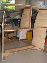
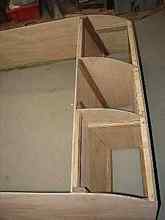
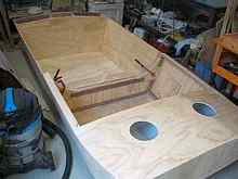
The picture below is a good example of that visualization. The forward module is taking shape, and although it looks more like a box than a boat, size and internal volume can be clearly seen.
|
Forward Hull Framing Complete, Minus the Base and Deck |
At this point things are beginning to come together as expected, and Michael is deliberating making some changes to the assembly. As this boat will also be used by his grandchildren, he is justifiably concerned about their safety. Larger boats tend to have foamed-in buoyancy compartments for such a purpose, and Michael has determined that creating such space within the existing compartments is doable.
Placing supports halfway up the inside of the forward compartment, and then covering the opening with plywood would provide a fixed volume that he could fill with expanding foam. This deviates from the plans, but does not, in any way, detract from the overall integrity of the design. Only a few extra pounds were added to the module, and probably will provide even more structural strength than the original design. Photos on the following page shows the enclosed Forward Module.
|
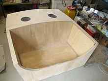
This is the completed Forward Module, with decking. The 2 holes are access ports to the interior, and will have watertight hatches applied. The foam occupies about half the visible volume. |
Progress will now shift to the Aft Module. As the basic frame assembly is the same as the Forward Module, and as little resistance was met regarding faulty dimensions, building time was shortened, and the boat is taking shape. However, one major hurdle remains, the base assembly.
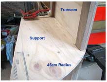
The next photos will outline the task of applying the base to the Aft Module. This is probably the most difficult part of the whole assembly, as Michael will attest to. It requires that the plywood be bent around a 45cm (18") radius at the transom. This necessitates the plywood be kerfed in order to bend this sharply. The drawings specify a 3mm (1/8 ") deep v-groove every 2 to 3 centimeters. In fact, Michael had to make them every 1-1/2 cm, and even then the task was challenging.
The purpose of the radius, instead of a square end on the transom, is to allow the water a smoother exit from beneath the hull, thereby reducing the drag on the aft of the boat. This is where design philosophy meets reality. The builder ends up paying the price of a difficult process.
|
I added framing timber to the bottom of the transom. I then planed this framing at an angle to meet the bottom panel. This allowed me to have a greater surface area for gluing, and to use screws to hold the panel in place. This led to a stronger joint, and less chance of it moving while drying.
Michael
This is an upside down view of the Aft Module. |
Plywood tends to bend better on one axis than the other. Depending on the grade and number of layers making up the plywood, bending over a sharp radius can be difficult. Michael has chosen good plywood, but it looks like the primary grain (where the plywood bends the easiest) is lengthwise, rather than crosswise, which would be an easier bend at the transom.
|
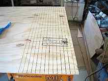
This was Michael's first attempt, per the plans, at kerfing the aft of the base panel. After attempting to bend it over the radius, he had to add new kerf cuts between the ones shown. Finally, he was able to achieve the bend, but not without much stress (on him and the plywood). |
|
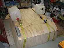
Here we can see the necessary steps taken to insure a good bond of the base to the module assembly. |
Now that Michael has worked past the most difficult assembly, he could not wait to see what the finished boat would look like. The photo below shows the completed forward module, minus seats, clamped to the rear module, still incomplete, but showing great promise.
Next will be the addition of a preservative in the rear module buoyancy compartment. This is necessary because the space will be sealed when compete, but dreaded moisture could creep in, so sealing it now is a must.
To be continued tomorrow ...
|