 Custom Search
|
|
| sails |
| plans |
| epoxy |
| rope/line |
| hardware |
| canoe/Kayak |
| sailmaking |
| materials |
| models |
| media |
| tools |
| gear |
 |
 |
| join |
| home |
| indexes |
| classifieds |
| calendar |
| archives |
| about |
| links |
| Join Duckworks Get free newsletter Comment on articles CLICK HERE |
|
|
| Back to Building Part Four: The End is Nigh |
by Kevin McNeill - Ladysmith, British Columbia - Canada |
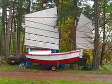
Here we are at the new building site. The house you can see at centre left is my daughter's place and the nearest power source. Luckily Costco had heavy duty 100' extension cords on cheap. I only needed two but I have to haul them back and forth so they don't get run over by the lawn mower when I'm not there.
The shed itself went up quickly and is nicely situated in the shade and I can use the front cover as a leanto over my truck for inclement weather of which we get more than our fair share.
Do not be fooled by the sunshine, it's only a trick to get you more than 200 metres from your truck before it starts to rain. Prior to moving I had finished the tiller mechanism the design of which I borrowed from the Navy whalers I learned to sail in. The whaler had a mizzen mast with a bronze collar that acted as the mast partner and the tiller yoke rotated about that collar. Not having the wherewithal to have a bronze collar manufactured I substituted a ¾ “ bolt.
The two arms are attached with wire strops to similar arms on the rudder head and the combination of the lever arms actually gives excellent control of the rudder. In the picture above you can see the tabernacle for the main mast and the daggerboard box directly behind it. I based this design decision on drawings of junks and even though the centre of resistance of the board is well forward of the centre of effort of the sails the large rudder should move the centre aft or at least that is the theory. In any event construction proceeded apace not with out some minor difficulties. For instance in the picture above you can see two small hatches on either side of the main bridge deck hatch. Those were necessary because I fastened the bridge deck in place prior to putting the ballast tank tops on. I realized that my arms were too short to reach the outboard edges of the ballast tank tops to fasten it down. Necessity being the mother of invention, I've decided to put ice boxes under the bridge deck on either side. By November it became too cold to really do any work out side and by then I was at the final fit and paint stage. So over the winter I built various boat bits which I added to the boat in the spring.
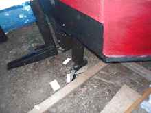
I am by nature a scrounger type of guy and if I can find something to use that approximates the thing I want and it is of course way cheaper then that's what gets used. The rudder fittings are a case in point. The gudgeons are gate hardware as is the lower pintle. Fitting the lower pintle was again one of those things that did not go quite as planned. When I drilled the pilot hole for the pintle the drill bit went in only so far and then wouldn't go any further. In the picture you can see a line of PL Premium about 2” up from the keel, that is the join between the keel strip and the skeg. Driven through that strip were two ceramic coated 3” deck screws which passed at angles through the path of the drill bit, tough coating that ceramic. Anyway, I had to back the screws out, redrill the hole, pump it full of PL and then wind the pintle in. It's going to need repainting. The upper pintle however was a piece of cake as all I did was use two gate hinges as gudgeons and put a 3/8” bolt through them both with a hairpin through a hole drilled in the bolt.
My original intention was not have an engine but saner minds prevailed. I bought an old electric trolling motor, took it apart and built a fairing around the post to the motor and mounted the entire thing in a slide in the rear well. The motor control was stripped, refurbished and mounted in a box of the forward side of the after bulkhead. The slide moves up and down by means of a short lanyard and there are stops at the bottom of the slide to prevent me from dropping the whole works into the ocean. Known in naval circles as not a good thing. In the picture below you can see the motor in the top right, when it drops down it is even with the bottom of the rudder.
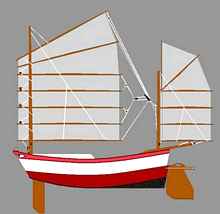
Before we start on painting and the colour scheme the ghastly colour you can see above is primer, so there. Once Spring arrived painting began in earnest but when you're on call 10 days out of 30 and family and spouse want other things done getting to the work site is another matter. The colour scheme for the boat was under some discussion. In the end I decided on this.
Well it's not strictly true that I decided, I have been accused over the years by my spouse of being colour blind, which I am not, you can't be in the Navy and be colour blind, she disagrees. Thus any colour decisions must be run by the Colour Deciding Committee of which I am not a voting member. I decided to work from the inside out starting with the cabin. It's not as big as I thought it was and my knees took quite a beating. Painting the cockpit was relatively easy. I must admit I am not the world's most careful painter and so the edges aren't up to professional standards but it works for me. I like Andrew Linn's solution, if it looks good from 20' it's good enough. I used 100% acrylic latex exterior house paint throughout and that worked well.
Once the inside was painted I fitted the cockpit seats and seat backs which had been constructed over the winter.
I waited to paint the cockpit sole until the seats were in place because without the seats I would go right through the flotation tanks. Not a good thing. You can see the control box for the motor just under and to the starboard side of the tiller. Once the painting was done then it became time to rig. As a scrounger I am always on the look out for useful bits. At our SAR hall were several pieces of aluminum angle deemed useless by the boys, they became very useful for me.
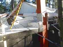
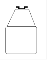
Two pieces formed the mast partner for the mizzen mast and another became part of the mast step for the main.
I must admit that this latter creation may have been a tactical error on my part. To remove the main mast you first lift up on the mast to clear the step. The upright edge that you see is about 3” and the mast fits very tightly in the tabernacle, it's not as easy as I envisioned. Nor is it as easy to haul the mast upright as I calculated. But inventive minds find ways, in this case an 8 to 1 haul system, white lithium grease and a strong son-in-law.
In the above picture you can see the lower attachment of the main halyard starboard of the tabernacle. The halyard itself is a retired SAR 11mm rescue rope. This is ideal for a halyard as there is less than 5% stretch and more ideal from my point of view because it was free. Rather than have the 3 to 1 at the top of the mast with the associated weights, I seized a 3”carabiner to the halyard, hooked the upper block to that and made it a 3 to 1 downhaul. The block you see to starboard of the down haul proved to be less than successful so I lengthened the connection between the lower block and the eyebolt so that the hauling end goes back over the cabin top. Less friction equals less work. The black stripe you see going from the upper left of the picture down to lower centre is the haul strap for the trailer. I found that by using the 8 to 1 to keep the mast in the raised position and connecting the trailer strap to an eyebolt on the butt of the mast I didn't need to have the strong son-in-law always at hand to raise the mast. By November it was 99.9% finished but too late to launch. A dry run with the sails showed a slight problem with peaking. The mainsail halyard connection was too far forward, a result of the builder second guessing the designer's plans. The solution was to move the strop aft or to add a peak halyard. Having made a beautiful wire strop with a rawhide saddle for the original connection I didn't feel like cutting it and making another one so I opted for the peak halyard the end of which I fastened directly to the carabiner described above so they both go up or more correctly down together.
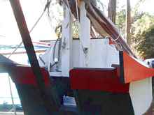
The mizzen mast/sail was more of a challenge, it's a modified gunter and the yard ran up on a wire jackstay with two rings around the jackstay. This turned out to be impractical and resulted in the drooping of the peak evident here. While I was mulling over this problem I continued to read Duckworks and lo and behold in one of Jim Michalak's semi monthly columns the solution was presented. Jim had the same problem with a gunter rig he was using and finally solved it by using a short piece of mast track on the back of the mast to guide the gunter yard. I needed to offset the track from the mast by about an inch and a half which was the reason for using the wire jackstay in the first place. I added a truncated triangular piece to the back side of the mast and fastened the mast track to that. It works a treat.
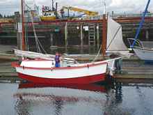
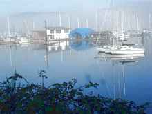
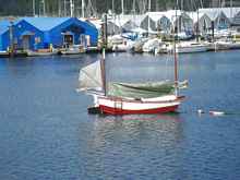
Now I just had to wait for better weather and it came in April however the social secretary had decided that we needed a holiday and that driving down to Palm Desert and back would be just the ticket so April was out. May came but I was on call for most of it so not able to launch any boats. I had a window of opportunity at the end of May and took advantage of it and on 29 May 12 into the oggy she went. That's my favourite small sailor directing operations from amidships. She came off the trailer with no problems and settle right to her lines as drawn. What you can't see in this picture because we're down behind a breakwater is that it was blowing force 5 (moderate waves of some length, many whitecaps and mall amounts of spray, branches of a moderate size move and small trees in leaf begin to sway). You will recall that the only motor is an old trolling motor reputed to have 30lbs thrust. Well it turns out that is not enough to push this boat against a force 5 wind and when you're 50 metres from the breakwater it is not the moment to see how she sails, especially when you discover that the daggerboard won't go all the way down. Luckily a passing boater saw my dilemma and towed me to the mooring. The daggerboard fiasco was entirely my fault. I filled the lower part of the board with marbles and then put expanding foam into the upper portion. It turns out that expanding foam is pretty powerful and can bulge 5mm ply to the point that it is wider than the daggerboard slot in the keel. So there you have it. If I added up all the time that I actually worked on the boat it would probably amount to three or four months of full time 8 hours a day. But it took three years. I am entirely satisfied with the result and look forward to many years of enjoyable sailing in and around the Gulf Islands. Two last pictures, the first is of Ladysmith harbour looking at the Ladysmith Maritime Society marina. Kuai Le's mooring is the red and white post to the left. This was taken in February. To the right and not visible in this picture is an area colloquially known to the residents as dog patch. It is a group of old and newish boats in various states of repair most of which are live-a-boards. Because my mooring is on the right hand side of a drying bank separating the marina from dog patch I am now a resident thereof and without them I would still be hung up on the breakwater. So a big thank you to Joe, his dog and his boat.
The second is of Kuai Le at the mooring. I need to work on that boom tent because the next day it rained and there was 6” of water in the cockpit.
For all you home builders out there it's this kind of picture in your mind that keeps you going. apricis diebus et bonum ventis [Latin: Sunny days and good winds]
|
_tn-s.jpg)
_tn-s.jpg)
_tn-s.jpg)
_tn-s.jpg)
_tn-s.jpg)
_tn-s.jpg)
_tn-s.jpg)
_tn-s.jpg)
_tn-s.jpg)
To comment on Duckworks articles, please visit our forum
|