 Custom Search
|
|
| sails |
| plans |
| epoxy |
| rope/line |
| hardware |
| canoe/Kayak |
| sailmaking |
| materials |
| models |
| media |
| tools |
| gear |
 |
 |
| join |
| home |
| indexes |
| classifieds |
| calendar |
| archives |
| about |
| links |
| Join Duckworks Get free newsletter Comment on articles CLICK HERE |
|
|
| Out There |
by Paul Austin - Dallas, Texas - USA Lofting Today - Part Seven |
 |
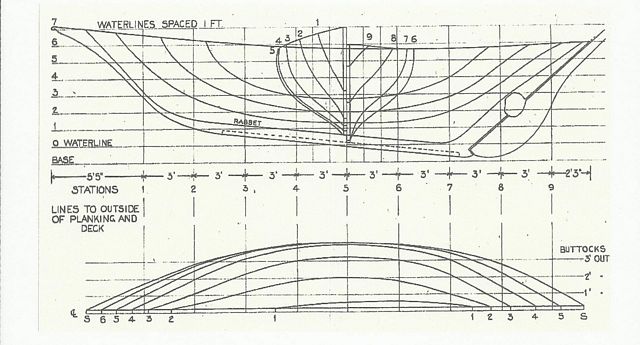
Part One- Part Two - Part Three - Part Four - Part Five Big Boats, Roofs, KeelsWe've gone through plenty of lofting techniques so now we can look at a big boat and its' plans. We will use a 33 foot Tancook schooner from D. N. Goodchild as our big boat, since it has such a simple shape of hull. It amounts to three lines curved into each other. Normally nearly all plans are drawn with the bow to the right, although I find this disconcerting considering I write left to right. I'd prefer the bow to be on the left, and with the Tancook schooner it is, so let's begin.
These are our plans on the plans sheet. We'll begin with the four great lines-stem, keel, stern and rabbet.
The black line is our stem, keel and stern, and the red line is the rabbet. Those lines have to be just right. I've made them thicker than they would actually be, just to see them.
The next line that has to be right is the ballast line. I've put it in blue. Fortunately it hits a waterline and then crosses 7 lines. The stem, keel, stern, rabbet and ballast line can be put in with the table of offsets, a 10 foot straight edge and long compass. The old yards would use ice picks to pin down points on the waterlines and station lines, then bend battens that had been shaved to different thicknesses for different degrees of bending. Nowadays we use nails. And that curve aft of the ballast where the rudder will tie in probably could be faired in by hand and eye. You can add lines, every 6 inches horizontal and vertical, or just draw it in. The construction plan sheet gives us more information and three problem areas. The first is the bow piece shown here. It doesn't have enough measurements on this sheet or the offsets, so the designer expects us to draw it in as well as we can. As long as our waterlines are drawn the correct distance apart, this should be no problem.
The second place is the joint between the stem and keel. Since this joint is below the waterline, it has to be just right. I've put in what I think is a good bolting scheme. However today we might not use through-bolts but long screws with glue. I would give the shape of the knee a slightly convex curve, so that as we tighten down the screws or bolts, to presses tight against the stem and keel. Some builders will want to put a stopwater here. That's probably not a bad idea. The dotted lines are the inner and outer rabbet, which we will deal with later. All of these lines go in routinely.
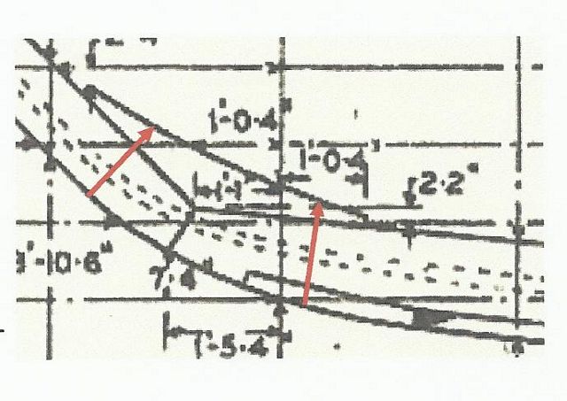
The third place where we need to be sure of ourselves is the meeting of the keel and stern. It has several small pieces which have to be put in strongly, even though they are small pieces.
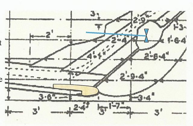
The hole in the rudder is for an engine, so I have put the shaft location in. You can see these small pieces don't have all the measurements you'll need, so just like the stem piece, you are expected to draw them in, add lines every 6 inches apart to finish the job. I have colored in a piece which has a steel dowel in it and in the rudder upon which this huge rudder pivots. This has always seemed to me too fragile, but this schooner has been built according to plans, so it must work. The rudder also has gudgeons along the stern. With such a degree of rake, this rudder becomes heavy. The keel has been made the soul of simplicity. It's just a rectangular straight-sided box. No need to make layers or plank on frame forms. A simple rectangular box will do it. One note about long keels. The further away from the plank rabbet line the are, the more tipsy the boat will be in light wind or at anchor. A keel with weight well below the planks is great for blue water cruising but it sways the boat at anchor. All the other lines of this fine hull are done according to the methods we have been looking at, so there should be no trouble. +++ However, not all boats are this simple, especially today when boats are made of different materials. The Construction Plan sheet might not show us the details we need. So we have to rely on the designer to provide more details on another sheet. In this hypothetical case, it is the
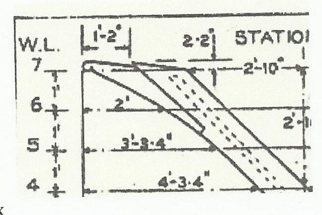
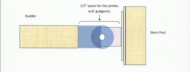
manner in which this long, heavy rudder is attached to the stern post. There has to be enough
space for the rudder assembly to move in both directions. Paint takes up some of the space here, and that must be taken into consideration. If nails are used as a fastener, they take up space also. So the thicknesses and clearance needs to be specified or scaled. Sometimes a designer will change scale on a detail because he is putting it on the same plans sheet. When he does that, he will supply the dimensions for you.
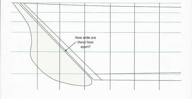
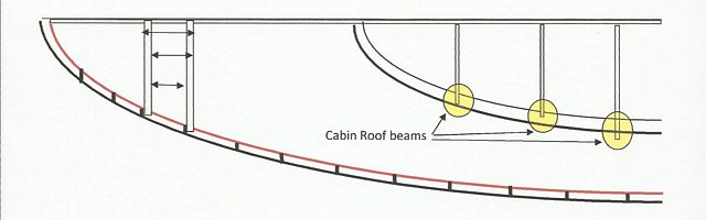
If you're building a boat with curved planks which require molds spaced close together, you'll have to know how the measurements between molds were taken. They might be outside face to outside face, outside to inside or inside to inside face. For instance:
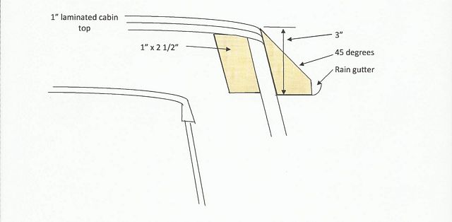
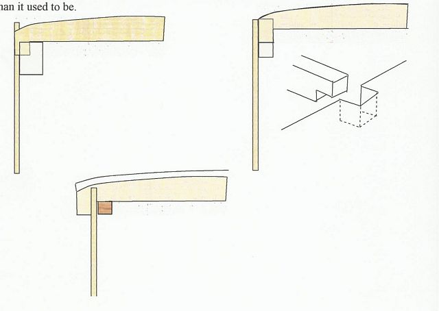
The plans will have to specify. In previous decades, a detail might show how the frame distances are to be made. Today, it might be listed in a legend in the corner of the plans. For the cabin roof beams, the plans will have to specify how they connect to the cabin sides. Some are let in flush with a cut opening, some are flush to the inside with a support member The red line is the deck clamp, usually 2" thick. It will need to be scarfed on boats more than 18 feet or so. Finding a 2" plank longer than 16 feet, and then finding a box to steam it in is harder than it used to be.
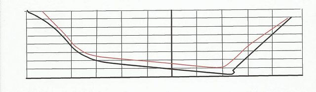
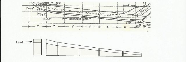
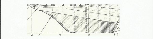
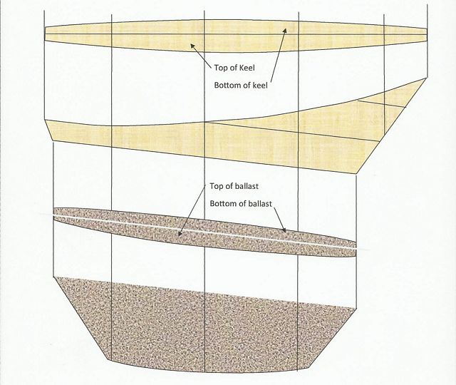
Keel ballasts are a world in themselves. They are easy to loft and frame, but they require special preparation since you are dealing with very hot metal temperatures. Many builders will take the lofting to a foundry for the metalworkers to do the job. This involves building a framework into which the molten lead or iron is poured. Some builders will build the framework themselves and pour the metal themselves. It can be less trouble and delay to do it yourself right there with the hull. Broadbill has a simple, nearly rectangular ballast, which would be easy to loft and frame. It is 5" thick by 20" long, with a slight turn at the stem/keel intersection. The plans don't even have a ballast lofting page, since the dimensions and shape are the lower keel face.
Here, the shape of the box is taken from the profile view above. If the ballast is poured there at the site, the blue box is built to sit on the ground with the 5" wide by 5" deep keel poured into it between the bulkheads. In this case the ballast bar could be made straight and then bent to fit the keel shape, since the bend isn't much. Then more ballast is put inside the hull, between frames. But that's a simple one.
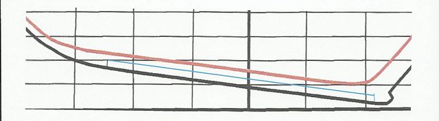
Now this one from a 20 foot daysailer will take some shaping and a more complicated box. You can see the long bolts, which require accurate spacing and placing to drive them through the ballast and on through 3-5 feet of oak planking. This not only is classy work, it is hard work. To keep the pressure on the drill as you go through metal and wood is a job for a young hearty man. The lofting is the key. It has to be accurate and full sized. This iron ballast is formed and poured at a foundry. Then, when the hull is right side up the ballast is rolled under the hull with bolts driven in and sticking up. Then the oak planks, with bolt holes already driven, is lowered down on top of the iron, bolts through the holes in the oak. With this assembly ready, it is jacked up far enough for the bolts to go up through the keel to bolt floors, 3" x 4" in size on the inside of the keel.
I've left out the bolt placements and measurements that would be on the lofting, so you can see the entire operation together. I've never liked outside ballast. I don't think it's worth the trouble, but if you're sailing offshore or across a sea it is the way to go. In light air or at a mooring, ballast hung below the hull will sway the boat, but at sea it's necessary. Paul This is Paul's Blog: https://crossingthoughts-paul.blogspot.com.au P.S Paul now writes with Mike John on the History of Science HQ: Paul is also publishing his books on Amazon. *****
|