 Custom Search
|
| sails |
| plans |
| epoxy |
| rope/line |
| hardware |
| canoe/kayak |
| sailmaking |
| materials |
| models |
| media |
| tools |
| gear |
| join |
| home |
| indexes |
| classifieds |
| calendar |
| archives |
| about |
| links |
| Join Duckworks Get free newsletter CLICK HERE |
|
|
| Out There |
by Paul Austin - Dallas, Texas - USA Lofting Today - Part One |
 |
| Part One- Part Two - Part Three - Part Four - Part Five
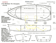
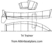
First I'd like to thank Mrs. Pat Atkin for her generous permission to use Tri-Trainer as the simple skiff and Ken Simpson for designing April Love for me. I'd like to thank Tad Roberts for his help with expanded transoms. This is not a subject you could ever master by yourself. And I need to thank the guys on the Wooden Boat Forum who gave their time and experience. Now as to, 'Why loft?' Although many boats are built without real lofting, even the best designers have made mistakes on their plans. A famous designer left a line out of shape on one of his best known designs, producing a hollow in the midframe area. A builder who had come to trust the designer built the boat with that line out of fair - he didn't use the lofting to make the correction. The lofting floor is the place to make sure the boat comes out as you hope it will. So a basic grasp of lofting is still useful. And it can help you transform a set of lines into a model. It can help you come to decide whether you want a particular boat. This is true if you are a buyer or a builder. After you have lofted a boat, you really know it, before you go get the lumber with your own money. And I've done this about lofting just because I really enjoy this. To me, this sure beats television and bad preachers. Most everything here will be old hat to Duckworks readers. I hope the fellow who is looking at lofting for the first time will look here, as the place where he can get encouragement. Today weekend whackers like myself don't really do lofting, although designers make use of it. Below is Ken Simpson's TOTER 2, put in the traditional profile, plan and half-breadth view on plate 3 of his plans compared to the traditional style of an John Atkin skiff.
So designers do the lofting for us, laying out on the plywood sheet the measurements. In a sense we do the lofting from that point on, using the tried-and-true method of establishing a point in the lower left corner of the plywood, measuring from it and cutting. But the traditional style of half-breadth, plan view and profile lives on in model ships. You could take the lines on the right, scale them for a 2 1/2 foot model and build with, say, three frames spaced throughout the waterline. With a sheet of 1/8 inch balsa or similar wood, you could have your own model without buying expensive plans. So for modelers and students of design, I'll go quickly through the lofting of this Atkin boat. Let's get started. I've chosen an Atkin small boat because the shape is easy to see. The basic idea of lofting is to establish a scale on the small drawing, put some lines in to measure exactly and then put the same lines in on a larger scale on a large sheet of plywood. In lofting bigger ships, the details are numerous but the principle is the same. We begin with a flat floor longer and wider than the boat. I think two feet wider on the sides and two feet longer is the minimum space. We will have to walk around the space, lay tools down, maneuver our selves around it. So for the 10 footer, 12 feet long and 10 feet wide is what we need. This might seem too much. I'm used to putting plywood on a table, making measurements and cutting. But in traditional lofting we draw on the floor full size and then make pieces from those drawings. As a result we need the space. If the floor is not perfectly level, we'll have to shim up the plywood that we lay down. In these early stages of lofting, measuring perfectly is essential. It saves making up for the wrong dimension later. Nothing I hate more than going back to the lumber yard I just went to this morning. I don't want to face that fat manager in the plywood aisle who's laughing when he sees me again, his hand out for my plastic. So with our level space we can put down two sheets of plywood, butted tight together on one end. Here is our drawing on paper from which we'll build.
What we'll do is get a scale. Most scales on plans are 1" for 1 foot or something similar. Then we'll go to the plywood having converted, say, 2 inches on the plans to 2 feet on the plywood. First, below we put in two perpendiculars which I have in red and a baseline which I have in blue. Actually the baseline is the bottom of the plywood but I put it in blue anyway. The perpendiculars have to be pretty darned perfectly upright. I would check the baseline for straightness, since off of it will come other lines.
With the bottom left as the starting point, we'll measure up and over for the first point with a T-square and pencil. Then we'll drive a nail at that point where I have put a tiny star. When all the nails are in, we spring a batten around the curved sheer and bottom to draw the line. Then we lay the batten along the stem and stern nails to draw straight lines. That will close this profile view. Finally come the frames from the image above, although we don't need all of them. I put in frames 2 and 3 to stay in the boat as seat supports, and frame 1 to take the pressure off the planks at the bow.
This view also gives us the heights of each frames. But to cut the frames we need the widths also and the flare of the sides. So for that we have to put in the half-breadth view over the profile view. I have put H for the height of Frame 3 and the widths of that frame. You can see the height is taken off the profile, in blue and the width off the half-breadth in black.
We don't really need to have the dimensions listed for us, we can figure them out with our scale. What we have to do is draw the frames right in the middle of our hb (half-breadth) and profile view. We begin with a centerline through the center of both views. We will measure off of this line. This view will be called the plan view.
The distance of vertical 1 becomes horizontal 1, and when you measure from the baseline up to the sheer along that frame (v2) that distance up becomes the distance out, horizontal 2. The same 'measure out from the centerline to measure up from the baseline' procedure goes for all the frames. On this boat, the frames are not an equal distance apart. If you've got plans in which the frames are an equal distance apart, the measuring is a little easier. This is the basic stuff of lofting. It's not difficult, but it all depends on good measuring, straight baselines and centerlines and a good batten for the sheer and bottom chine. When we want to graduate to a V-bottom boat, the upper chine line goes in on the profile view so we take an extra measurement with the same procedure. If we have a round bottom, then we add another line, called a diagonal to give us another point to draw our frame outline through. So let's go on to a full drawing. Here we have the frames in and a waterline. This is what traditional plans will look like. Now we'll draw it again with a second chine, not in the original plans. You'll see the same method of including the second chine, another line but same method.
The first thing to do is draw black straight lines down from the stem and stern where the new chine begins and ends. Then I'll draw the chine 2 line connecting those two points in light blue. Now I can use the same up-and-over method with one more point, the new chine.
The three distances up from the baseline to the lower chine, second chine and sheer become three distances across from the centerline at the level at which the chines cross the frame. Same method, one more measurement. How far do you go up before going across? It's where the frame line crosses the chine lines.
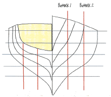
Now for the last set of lines. These are called buttocks. They are vertical lines through the frames parallel to the centerline. Veteran boatbuilders us them as much to look at how water flows under a boat as they do for lofting.
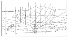
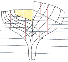
The farther apart they look in profile the narrower the hull. The closer they look together the wider and more round the hull. This is how the waterlines, diagonals and buttocks look when they're all together on a finished drawing. If you look at any one frame, just go up its' outline and you'll see how many points there are to establish the shape. The first frame off the bow has six. When I drew these lines, I didn't put in every frame, every 16 inches because this drawing is so small. However, on sheets 11x16 or full sized patterns there will be more detail. The work is labor, but it is not difficult.
To be continued next month... Paul This is Paul's Blog: https://crossingthoughts-paul.blogspot.com.au P.S Paul now writes with Mike John on the History of Science HQ: Paul is also publishing his books on Amazon. |
|
