
 Custom Search
|
| sails |
| plans |
| epoxy |
| rope/line |
| hardware |
| canoe/kayak |
| sailmaking |
| materials |
| models |
| media |
| tools |
| gear |


| join |
| home |
| indexes |
| classifieds |
| calendar |
| archives |
| about |
| links |
| Join Duckworks Get free newsletter CLICK HERE |
|
|
| Out There |
by Paul Austin - Dallas, Texas - USA Lofting Today - Part Five |
 |
| Part One- Part Two - Part Three - Part Four - Part Five Laying Down LinesNow that we know a few things, let's put them to work. We begin with the space in which we'll work and the loft floor. The bigger the boat, the more extra space we'll need. This is especially true if the hull will have to be turned over or put on a trailer after it is built. One book I read recommended the loft floor be 6 feet longer than the boat, 4 feet wider. Keep in mind the greatest freeboard, from keel to bow height. In small boats this will be close to the width of the beam, but in longer boats the freeboard might be greater than the beam. Now if you just don't have enough space, the lines can be drawn on top of each other to save space but you'll have to deal with all those lines crossing each other. A plywood floor is best. It can be of a cheap grade of plywood, providing you paint it with 2 coats of semi-gloss paint and sand it smooth.
David McIntosh says if the loft floor is your living room or a rough shop floor you can put down a roll of sheathing paper, let it sit for a day and then tape it down. Living room? There are different ways to draw the lines-what is essential is the lines must be straight and at right angles. The best way to check the lines for 90 degree angles is with a compass.
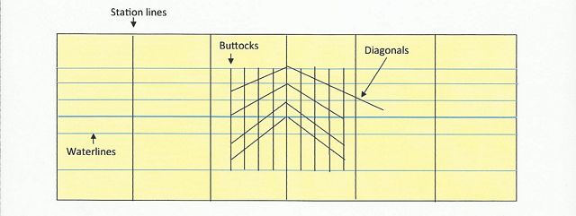
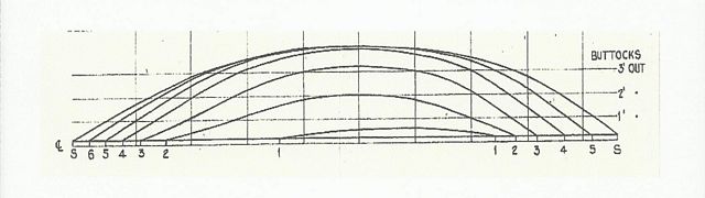
Some of us have chalked down these lines. Old School builders would make a straight edge 16 feet long. Then they'd stretch down tight a nylon string and mark with two lines shaped like a T right there alongside the string. Eventually the chalk will disappear but do what you want. Take a day for these lines. They will make the boat easier to build or harder, depending on the squareness and straightness of the lines. There are a few shortcuts. If you put the station lines in where the boat frames will be you can save some time, but some boats vary the distance between frames. Diagonals should cross two buttocks at least; diagonals are numbered from the lowest one-D1-to the highest one which in my drawing is D4. Usually the bottom 2 or 3 diagonals will cross the square made by the station lines and the waterlines, like this:
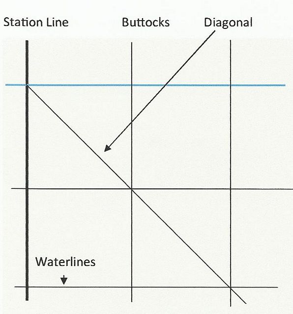
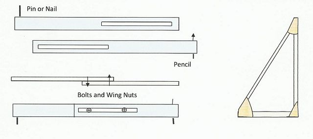
Keep in mind that different designs will have diagonals in different places. Some builders like to put the diagonals in after the shape of the frame has been drawn in. Every diagonal will hit an intersection of a buttock and waterline-some close by as in this drawing and some several feet away from the station line. By now you know you need a string line, a straight edge, a big compass and a tape at least a few feet longer than the stem to stern measurement. A square is essential. If you're building a big boat you should make your own. Use 1"x4" pine thick enough to be stiff but thin enough to handle. A cross brace will keep the square in shape, but glue it. Just remember to have both members of the square glued so they can lie flat on the floor. Still, if a measurement has to be exactly 90 degrees, the old high school compass method is the most reliable. If you need a big compass you can make it yourself or buy one at a drafting supply house.
You'll also need plenty of battens. Drafting houses have plastic battens, which are used for tight curves. Wood battens are used for straight lines or a sheer without much curve to it. Most builders use pine since hardwoods tent to remain in something of the shape in which they were bent. It's good to have one square batten more than the length of the boat, 3/4" for small boats, 1" for bigger ones. When you scarf battens the ratio of length to width is 20 to 1. Professional builders paint their battens a non-glossy black so that the grain of the wood does not show through, obscuring the exact line you're looking at. It seems like a small point, but having pens and pencils on hand is good. Builders have blurred lines with wet feet, so use waterproof pens and markers. I have bad knees so I have to have kneepads or a small stool to do this much bending over. I have used measuring sticks made of wood rather than metal tape measures. Tapes do bend and wrinkle and the end piece does move away from its fastener. Professional builders have plenty of 6" blocks for station lines, provided the blocks are precisely cut. Some builders use weights to keep battens in place. Weights are especially useful in laminating stems which have to be bend substantially. I once asked Melbourne Smith, who designs replicas of 18th century ships, what tools he uses on his drafting board. He said he uses small weights even on his 3x6 foot drafting board.
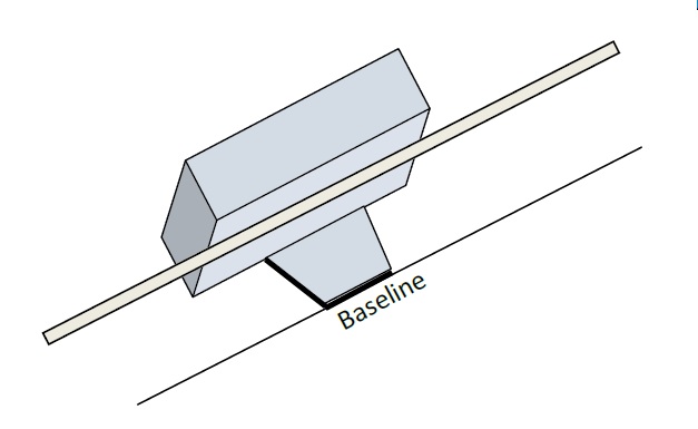
Drawing Lines The baseline should come first. But it doesn't have to be a line at all. Some builders put their biggest batten there so they can butt against it all their measuring tools. I like this idea but with computer generated lines I don't know how often it is done these days. Anyway the baseline comes first. If you want to draw a line, there is a method many use. You stretch a cable an inch over the painted plywood and run a jig along the cable with a pencil pressed against it. I think this is fraught with possible errors, but we do these things. A pencil point is put in every few feet, then the points are connected with a long batten. Still, I think a baseline batten is easier and less conducive to errors.
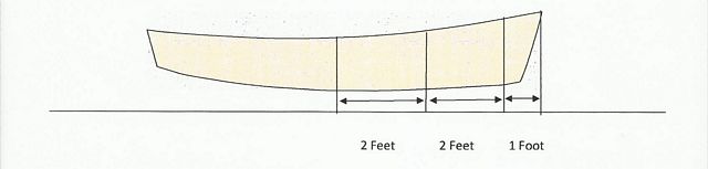
iNow we can go to the station lines. First, make sure the first and last station lines leaves you room to draw outside the stations. Not only is this for the sake of getting an accurate line, but some boat transoms hang outside the last station line. You begin by marking station lines on the baseline. Many builders use their metal tape measure to do this but I'd use a measuring stick-provided it is accurate. Fewer steps, fewer errors. Different plans will specify different lengths between station lines. The plans will have the dimensions written on them. Usually small boats have 2 feet between frames in the middle of the boat, but the distance from the most forward frame and the bow might be less. The same goes for the distance between the most aft frame and the transom.
In bigger ships there will be many more frames than station lines. What I've done in the past is put the frames in that support the seats, then leave them in the boat. This isn't always possible, it depends on the boat. Lapstrake boats may specify more frames than 2, glued lapstrake leaves fewer frames in the boat than traditional nailed laps. These station lines have to be 90 degrees to the baseline. So when you put them in you can check them with the arc method we used before on each station line. Then where the arc crosses the station line, lay a batten across from the bow station line to the stern station line; it should cross each arc of each station line pretty accurately. If that's what you have, grab some rum and down it-you did it right! After you've labeled the station lines above and below them you can go on to the waterlines. The designer will specify how far apart the waterlines should be. I have found a measuring stick is easier than a tape measure. You may have noticed I made each waterline in blue. That helps me disregard any other lines laying across my view when I put waterlines in. Then comes the buttocks. If the boat you are lofting is lapstrake or cold-molded or carvel, I think buttocks are significant enough to make the line thick, so it will stand out. When it comes to the body plan, most builders will use the station line of the widest beam as the centerline of the body plan. If you used a stick for the buttocks before now, you can use the same stick in the body plan. And with the diagonals, the Old School practice was to begin the diagonals on an intersection of the body plan centerline and a waterline. The diagonal always ended on an intersection of a waterline and buttock in the profile view. However, nowadays a designer might not show that on his plans. He might simply specify an angle for the diagonal. The comes the sheer line in profile and the deck line in the half breadth view. These are long lines which require the first real fairing. When you put nails down on your measurements you'll have to choose a good batten and look at it several times. Now we come to the frames in the body plan. These can be drawn to accuracy in different ways, but I think the Old School Way of using a measuring stick involves the fewest steps. This method takes a long batten wide enough to write on in pen or marker.
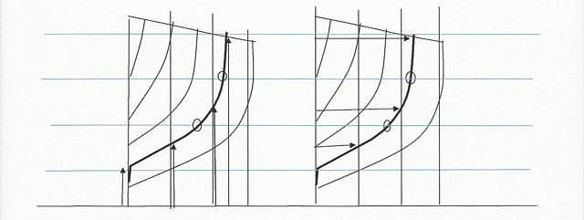
On one side of the square stick you mark the distances up-one the other side you mark the distances out. Of course you label each side of the stick as to which it is. On the left the offsets will be from the centerline below up three buttocks and up to the sheerline/frame intersection. In real life there will be more points, including measurements up to the waterline/frame intersection in two places on the left and out on the right. I've put circles around these additional points to keep the drawing from getting too cluttered. If the stick method doesn't work for you, use any method you want. When you first draw the frames in with their curves, it's called roughing it in. If this rough line is not fair or not where you want it, builders say check the distance between waterlines and the distance between buttocks Then fair the frame. If you have more than one frame to be faired, some builders get frustrated if they wait until all frame are roughed in. By that time, they have so much fairing to do. If you do one at a time, it might not seem like so much work. At this point the frames are roughed in. Before you do the real fairing, it's good to make sure the distances between waterlines and the distances between buttocks in the plan view are the same as in the half breadth and profile view. This can be done with one side of a smaller square stick, providing it's really straight.
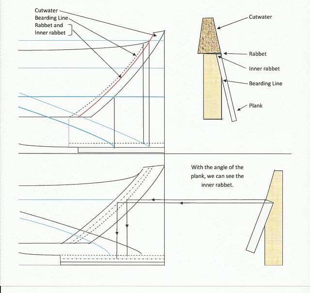
Now you're ready to bend a batten around the nails you tapped in on the body plan. If you like what you see, it's good. If you don't-and you have to move the curve of the frame-remember that new shape has to be transferred to all three views. And if you move the buttock or waterline to get it right on the curve of the frame, then that new position of the line you moved has to be changed in all views. Either move the new curved frame or move the line to the new curved frame. If you're not a professional at this, move the frame. I won't venture a guess as to which causes fewer problems. It might depend on the boat. At some point, you'll say, 'This is precise enough.' In the end, it's what the boat looks like when you've got the frames braced to the keel, and lay battens up there, to see what you see. If you like the curve of the frames, shaving off another 1/32 of an inch might not be worth the trouble to make it match the offsets. It's the boat that goes in the water, the offsets go in the closet. When we come to the keel, we have choices. Beginning at the stem, they come in two types which I have shown here. With the first, the rabbet and inner rabbet are so close in a line they won't show on the profile.
If you're living right, you'll get a keel like this, 5" wide for the entire length of the keel and 12" high-no curvature at either end. But that's only in your dreams for most boats.
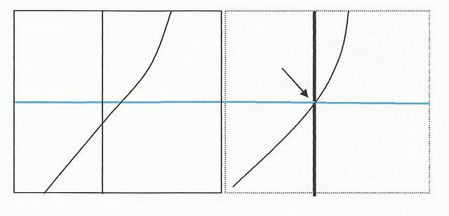
Nearly all keels will taper. Not only that, on the plans the designer will have his widest thickness and the keel rabbet. And if there is a lead ballast, he will have the bottom lines for it right there with the keel lines. This is a typical keel lines plan. I've exaggerated the spacing of the lines to make them visible. The black line is the centerline; the blue line is the bottom of the keel and ballast; the red line is the top of keel. The keel rabbet for planks is so close to the red line that I didn't show it. All of these lines will be in the offsets. The two most critical areas here are the first joint and the stem/keel area. The keel thickness must be enough to take pounding since so many designers insist on putting the first joint so near or under the waterline.
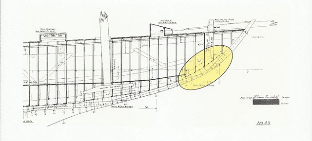
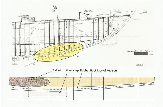
Another example of the joining work that has to be right is this from the most perfectly balanced ocean racing yacht by Francis Herreshoff, called Landfall.
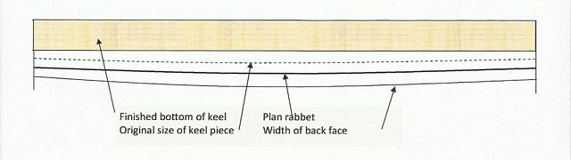
The stem knee that I have highlighted is 7'9" long, with 10 bolts. In this case the designer may give you a detail of the stem face dimension, the stem rabbet across the knee and the greatest width of the stem knee at its back face. Herreshoff himself often put in another detail. He wanted you to cut the stem from a certain dimension of wood so he put the original size of the stem wood, the beveled dimension and the rabbet and back face dimension. I have enlarged a drawing to show how this would be done.
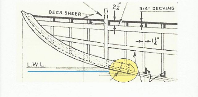
These lines will be anywhere from 15 to 30 feet lone, expanding for the keel ballast if there is one, lofted full size on the floor or given in the offsets, or both. With Herreshoff, the original keel dimension he called the ghost line. Evidently his shipwrights beveled it right on the boat, upside down. The second area of the stem/keel connection is the place where the stem really ends, meeting with the keel and ballast. Often this area is just under the mast, in a ketch or cutter. So let's go back to Landfall for an illustration.
With small boats the joint of keel, inner keel and planking can have more parts but they are smaller. You might have to get dimensions in one detail and extend the lines yourself for another. Don't you just love flat bottomed boats? Paul https://crossingthoughts-paul.blogspot.com.au P.S I am now writing with Mike John on: And, I am now offering books on Amazon. *****
|

|