Technical Details on How the Propulsion Force By Product is Produced
Part One - Part Two
To best illustrate the How the Principle works, I have provided four diagrams. The 1st three are designed to work together, as a sequence of illustrations. The 4th diagram, is a Classic Applied Force Diagram, which makes use of a right triangle, and trigonometry. The 1st three diagrams, should be sufficient to grasp the basic principle of How the Propulsion Force By Product is Produced, and applied to the Sailboat Hull.
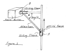 |
Fig. 1 |
The objective of Figure 1 is to provide a mechanical illustration of the of How the Principle, which Produces a Propulsion Force By Product, works.
Force Meter: The Force Meter has a pressure plate inside the opening. When a force is applied to the pressure plate, the Meter displays the applied force. The pressure plate inside the Meter, does not move when force is applied to the plate.
Siding Sleeve: There are two Sliding Sleeves; A, and B. Each Sleeve is able to slide along on a circular rod.
Armature: The Armature is a rod connected between Sleeve-A, and Sleeve-B, by a rotational pin.
Theta : Theta (Greek Alphabet Symbol) is the angle between the armature, and the horizontal circular rod. The value of Theta will always be in a range of 0 deg to 90 deg.
Sequential Scenario of Figure 1 :
* When a Force is applied to Sleeve-A, Sleeve-A will attempt to slide upward.
* Sleeve A, will transfer the Applied Force to Sleeve-B via the Armature.
* Sleeve B, will transfer the Applied Force to the pressure plate inside the Force Meter
* The Pressure Plate registers the Applied Force, and displays the result.
Scenario of Figure 1 :
When a Force is applied to Sleeve-A, Sleeve-A will attempt to slide upward. A portion of the applied Force will be transferred to Sleeve-B. The amount of Horizontal Force transferred to Sleeve-B, is directly dependent on the angle of Theta.
* Minimum Horizontal Force is transferred to Sleeve B, when Theta = 0 deg, and 90 deg
* Maximum Horizontal Force is transferred to Sleeve B, when Theta = 45 deg
* Less Than Maximum Horizontal Force is transferred to Sleeve-B, when Theta is less than 45 deg
* Less Than Maximum Horizontal Force is transferred to Sleeve-B, when Theta is greater than 45 deg
* When Theta is equal to 45 deg, the Horizontal Force on Sleeve B will be 50% of the Applied Force on Sleeve-A
* When Theta is not equal to 45 deg, the Horizontal Force on Sleeve B will be less than 50% of the Applied Force on Sleeve-A
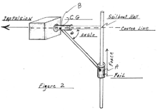 |
Fig. 2 |
Figure 2, is the same as Figure 1. The only thing that has changed are the identifiers.
Foil : Leeboard, Mizzen Sail, or Rudder
Force : The Lateral Force generated by the Foil
Sailboat Hull : The Hull of the Sailboat provides the frame work, at which the "Armature" transfers the Applied Force, at an angle Theta, to "Sleeve-B"; the CG located along the Center Line of the Hull.
CG : The Applied Force on the Foil, will always act on the CG location of the Hull.
Theta : The Angle between the Center Line of the Hull, and the "Armature" (radial line to the Foil). A maximum Propulsion Force By Product is Produced, when Theta is at 45 deg.
Propulsion : Propulsion, which is produced as a By Product, of the Applied Force to the Foil.
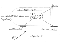 |
Fig 3. |
Figure 3 illustrates the sum of all three Foils, when they are applied to a Sailboat Hull. Each of the Foils will Produce a Propulsion Force. The sum of the three Propulsion Forces will produce a Net Propulsion.
Adjusting the Location of the CG:
The location of the CG, by definition of being a Sailboat, is going to be somewhere between the Leeboard (Centerboard), and at least 1 Ft. in front of the stern. Which means, that the default (dry boat) location of the CG, will initially be close to the location of the Leeboard. As cargo and crew are added to the boat, the CG will typically move aft of the Leeboard.
Note: By definition, a Sail boat, to retain Stability, must keep the location of the CG aft of the Leeboard (Centerboard). If the location were to move in front of the Leeboard, control of the Sailboat would be completely lost.
One of the easiest ways to determine the location of the CG, is to put the sailboat into calm water, with the sails down. Gently give the sailboat a push, such that the boat will begin to spin (rotate). As the boat rotates, look closely and observe the location which acts like it has an imaginary vertical axle through the hull. The boat will appear to be spinning on the imaginary axle. This is the default CG of the boat. As you add the crew, and cargo to the boat, the location of the CG will change (forward, or backward) from the default location.
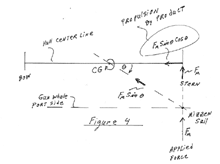 |
Fig. 4 |
Figure 4 is a Force Diagram, modeling the Mizzen Sail on the port side of the stern.
|


